Error code in Samsung Split Air Conditioner:

We have listed some of the most common error codes for Samsung ACs:

Here is the updated table with the information about the additional error codes you provided:

Error codeDescriptionPossible Causes and Solutions
E101, E102Communication Error (Interior Exterior)– Check the communication cable connections.
– Make sure there is no electromagnetic interference nearby.
– Check the condition of the cables and replace them if necessary.
E121Room Temperature Sensor Error– Check sensor location and replace if necessary.
E122Internal Pipe Temperature Sensor Error– Inspect and replace temperature sensors in the internal piping.
E154Fan Error (Indoor)– Check the status of the fan and its connection.
– Replace the fan if necessary.
E162EEPROM error (Indoor)– Consult a technician to replace or reprogram the EEPROM.
E163Option Error– Check the system configuration and make corrections according to the user manual.
E203Communication Time Out (Main Micom and Investor Micom)– Check connections and replace faulty components if necessary.
E221Outdoor Temperature Sensor Error (OUT-TH – Outdoor Temperature)– Check connections and replace sensor if necessary.
E231Condenser Temperature Sensor Error (CON-TH – Cond Temperature)– Inspect and replace the affected sensor.
E251Discharge Temperature Sensor Error (DIS-TH – Discharge Temperature)– Check connections and replace sensor if necessary.
E416Discharge Temperature Sensor Overheating– Check air circulation and make sure the system is working properly.
E422EEV or Valve Closing Error – Self-Diagnosis– Inspect the valve and its connections. Replace valve if necessary.
E440Prohibited Condition Error (Heating)– Check the configuration and operating conditions in heating mode. Adjust as necessary.
E441Prohibited Condition Error (Cooling)– Check the configuration and operating conditions in cooling mode. Adjust as necessary.
E458Fan Error (Outdoor)– Check the status of the fan in the outdoor unit and its connection.
E461Compressor Start Error– Check compressor starting system and make necessary repairs.
E462AC Input Current Limit Error– Check the AC input current limit and make adjustments as necessary.
E464IPM Overcurrent Error (OC)– Inspect the IPM power module and replace if necessary.
E465Compressor Voltage/Current Limit Error– Check compressor voltage/current limit and make adjustments if necessary.
E466DC-Link Low/High Voltage Error– Check the DC-Link voltage and make adjustments as necessary.
E467Compressor Cable Missing Error– Check compressor cable connections and repair if necessary.
E468Current Sensor Error– Inspect current sensor and replace if necessary.
E469DC-Link Voltage Sensor Error– Check DC-Link voltage sensor and replace if necessary.
E470EEPROM Data Error (no data)– Check the presence of data in the EEPROM and replace if necessary.
E471EEPROM Data Error (Main Micom and Micom Inverter)– Check the data in the EEPROM of the main Micom and Micom inverter. Replace the EEPROM if necessary.
E474Heat Sink Sensor Error– Inspect the heat sink sensor and replace if necessary.
E483Overvoltage Protection Error– Check voltage conditions and make adjustments as necessary.
E484PFC Overload Error– Review the PFC loading conditions and make adjustments if necessary.
E485Input Current Sensor Error– Inspect the input current sensor and replace if necessary.
E488AC Input Voltage Sensor Error– Check the AC input voltage sensor and replace if necessary.
E500Heat Sink Overheating Error– Check airflow to the heat sink and make adjustments as necessary.
E554Gas Leak Error– Inspect the system for refrigerant gas leaks and repair as necessary.
Error codeMeaning probable causeTroubleshooting
CL Auto Clean Indicator Indoor unit that produces odorsRun the “Auto-Clean” command to remove the odor.
CFFilter Clean/Reset Reminder Dirty filter Clean/replace dirty filter on your indoor unit
D.F.Automatic defrostingThe air conditioning is defrosting Wait for the automatic defrost to finish.
E3Indoor fan motor malfunctionDefective indoor fan or circuit boardReplace the indoor fan or circuit board, depending on which is defective
E4Forced defrosting Low coolant level, faulty pump, broken temperature sensor or pressure fluctuation Contact the nearest Samsung service center
E5Indoor heat exchanger sensor open/shortDefective outdoor heat exchanger sensor Replace the indoor heat exchanger sensor
E6Outdoor heat exchanger sensor open/short Defective outdoor heat exchanger sensor Replace heater temperature sensor
E7Heater temperature sensor open/short circuitDefective heater temperature sensorReplace heater temperature sensor
C2Inner pipe sensor failureDefective inner pipe sensor Replace the inner pipe sensor
E101Communication failed (indoor unit)Faulty power cables or connections around the indoor unitCheck for loose connections or power cables and fix them.
E102Communication failed (outdoor unit)Faulty power cables or connections around the outdoor unitCheck for loose connections or power cables and fix them.
HEElectric heater overheatedPower Overload Replace Heater Temperature Sensor or PCB
E201 Communication failed (between indoor and outdoor units)Loose connections or defective PCB (printed circuit board)Check for loose connections outdoors and indoors and if not, replace the main PCB
E1/21Room temperature sensor failureFaulty room temperature sensor Contact the nearest Samsung service center
E1/22Heat exchange temperature sensor failure Malfunctioning heat exchanger temperature sensor Contact the nearest Samsung service center
E1/54Faulty condenser or fan motor Replace the condenser or fan motor.
E1/63 defective EEPROM Replace the EEPROM

Error codes for Multi System AC Samsung:

Here is the updated table with the information on error codes for Multi System AC in indoor units and verification methods:

Error codeDescriptionPossible Causes and Solutions
E1-01Communication Error (inability to receive data)– Check the connection of the communication cable.
– Check the cable connection in other indoor units or indoor PCB.
E1-02Communication Error (outdoor unit cannot communicate)– Check the cable connection on another indoor unit or on the indoor PCB.
E1-21Room Temperature Sensor Error– Check the room temperature sensor and connection on the indoor PCB.
E1-22Heat Exchanger Temperature Sensor Error (inside)– Check the heat exchanger sensor inside and the connection on the inside PCB.
E1-23Heat Exchanger Temperature Sensor Error (outside inside)– Check the heat exchanger sensor outside the interior and the connection on the interior PCB.
E1-28Heat Exchanger Temperature Sensor (inside) detached error– Check the heat exchanger sensor inside.
E1-29Heat Exchanger Temperature Sensor (outside inside) detached error– Check the heat exchanger sensor outside the interior.
E1-30Heat Exchanger Temperature Sensor (inside and outside) detached error– Check the heat exchanger sensors inside and outside the inside.
E1-54Fan Motor Malfunction (inside)– Check the fan motor and wiring in the indoor unit.
E1-61More than 2 indoor units in cooling and heating mode simultaneously– Check the operation mode of other indoor units.
E1-62EEPROM error (inside)– Consult a technician to replace or reprogram the EEPROM in the indoor unit.
E1-63Option code configuration error– Check and adjust the option code as necessary.
E1-85Incorrect wiring– Check the cable connections between the indoor and outdoor unit.
E2-01Incorrect number of paired indoor units– Check the cable connections between another indoor unit and the outdoor unit.
E2-51Compressor Discharge Sensor Error (Short/Open Circuit)– Check the compressor discharge sensor on the outdoor unit.
E5-59Outdoor unit error– Consult a technician for diagnosis and repair of the outdoor unit.

Error codes for VRF Samsung:

Here is the updated table with information on error codes for VRF (DVM S) in indoor units and related communication and configuration aspects:

Error codeDescriptionPossible Causes and Solutions
E-101Communication Error in the Indoor Unit– Check the connection of the indoor unit and make sure it receives data from the outdoor unit.
E-102Communication Error between Indoor and Outdoor Unit– Check the communication between the indoor and outdoor unit. This code is displayed on the indoor unit.
E-108Error due to repeated address setting– Check and adjust the address settings as necessary.
E-121Interior Temperature Sensor Error– Check the indoor temperature sensor and connection on the indoor unit.
E-122Indoor Unit EVA IN Sensor Error– Check the EVA IN sensor of the indoor unit and the connection.
E-123Indoor Unit EVA OUT Sensor Error– Check the EVA OUT sensor of the indoor unit and the connection.
E-128The EVA IN temperature sensor of the indoor unit has detached from the EVA IN tube– Check the EVA IN temperature sensor and reattach it to the EVA IN tube.
E-129The EVA OUT temperature sensor of the indoor unit has detached from the EVA OUT tube– Check the EVA OUT temperature sensor and reattach it to the EVA OUT tube.
E-130Indoor unit heat exchanger inlet/outlet sensors are detached– Check the heat exchanger inlet/outlet sensors and reseat them.
E-135Indoor unit cleaning fan RPM feedback error– Check the operation of the cleaning fan and its connection.
E-149Error due to indoor unit AHU master sensor setting– Check and adjust the AHU master sensor settings as necessary.
E-151Error due to open EEV of indoor unit (detection 2)– Check the condition of the EEV valve and repair if necessary.
E-152Error due to closed EEV of indoor unit (detection 2)– Check the condition of the EEV valve and repair if necessary.
E-153Indoor unit float switch error (detection 2)– Check the float switch and its connection, repair if necessary.
E-154Indoor unit RPM feedback error– Check the operation of the indoor unit fan and its connection.
E-161Indoor unit mixed operation mode error; when the outdoor unit is preparing to operate in cooling– Check the operation mode of the outdoor unit and make adjustments if necessary.
E-162MICOM EEPROM error on indoor unit– Consult a technician to replace or reprogram the EEPROM in the indoor unit.
E-163Indoor unit remote control option is incorrect or absent– Check the remote control option settings and correct them as necessary.
E-180Simultaneous opening of cooling and heating MCU solenoid (detection 1)– Check the MCU solenoid and its connections.
E-181Simultaneous opening of cooling and heating MCU solenoid (detection 2)– Check the MCU solenoid and its connections.

Flashing lights on Samsung air conditioners:

Here is the updated table with information about the flashing lights on Samsung air conditioners and their meanings:

Light SequenceDescriptionPossible Causes and Solutions
Off – Flashing – OffRoom Temperature Sensor Error (open/short circuit)– Check the room temperature sensor and its connection.
Flash – Flash – OffHeat Exchanger Temperature Sensor Error (open/short circuit)– Check the heat exchanger sensor and its connection.
Off – Off – FlashingFan Motor Malfunction (indoor)– Check the fan motor and its connection.
Blink – Blink – BlinkEEPROM error– Consult a technician to replace or reprogram the EEPROM.
Blink – Blink – BlinkOption Error– Check option settings and make necessary corrections.
Off – Flashing – FlashingAbnormal Communication Error (Interior – Exterior)– Check the connections between the indoor and outdoor unit.
Flashing – Off – FlashingOutdoor Unit Temperature Sensor Error (Outdoor Temperature Sensor, Defrost Temperature Sensor, OLP Temperature Sensor, Discharge Temperature Sensor, Heat Sink Temperature Sensor)– Check the outside temperature sensors and their connections.

Regarding the display of the outdoor unit board error mode:

Lights (Yellow-Green-Red)DescriptionPossible Causes and Solutions
Off – Off – OffOff / VDD NG (No Power / VDD Not Good)– Check if there is power and adjust the power supply.
Off – Off – FlashingCompressor Peak Current (OC)– Check compressor power and make necessary repairs.
Off – Off – OnNG Communication (No Communication)– Check communication connections and correct problems.
Off – Flashing – OffCompressor Start Error– Check the compressor starting system and make any necessary repairs.
Off – Flashing – FlashingHeat Sink Sensor Error– Check the heat sink sensor and make necessary repairs.
Off – Flashing – OnNormal Operation– The unit is operating normally.

Leave a Reply

Table of Thermo King Alarms:

Green Thermo King AlarmYellow Thermo King AlarmRed Thermo King Alarm
It is a stored alarm. Indicates a condition that needs investigation but does not affect the unit’s operation. The alarm icon appears for 30 seconds when the unit is turned on and then disappears.Requires verification. This alarm is a warning to take corrective action before an abnormal condition becomes serious. The alarm icon will appear and remain on.Shutdown alarm indicating conditions that could damage the unit. The unit will shut down automatically, the alarm icon will appear, and the entire display will flash on and off.

Thermo King Alarms:

This table shows the alarm codes for Thermo King equipment, possible causes of the issue, and some measures to take.

  • Thermo King alarms are generated when the microprocessor detects an abnormal condition.
  • Multiple Thermo King alarms can occur simultaneously.
  • All generated alarms will be stored in memory until the operator clears them.
  • Document all alarm cases and communicate them to the service technician.
  • The Thermo King alarm table in Spanish shows all codes for all possible applications. Therefore, not all codes will be applicable to each individual unit.
  • The operator can repair certain faults, while others can only be repaired by the Thermo King dealer.
  • Some alarms may exist with Code 84.
  • The alarm may disappear automatically if the condition does not repeat.
  • Alarms that occur during a previous trip or a self-check of the unit will be preceded by a hyphen.
  • Some alarms are automatically self-eliminated when the operating condition that caused the alarm returns to normal.

Meaning of Thermo King Alarm Codes:

Alarm CodeEquipment Status Identification ColorOperator’s Action
Alarm Code 00Green = OK No alarmsNo action required.
Alarm Code 02Yellow Check the evaporator temperature sensor (zone)Check the temperature manually. Report the alarm at the end of the day.
Alarm Code 03Yellow Check (control) the return air temperature sensor (zone)Check the temperature manually. Report the alarm at the end of the day.
Alarm Code 04Yellow Check (control) the discharge air temperature sensor (zone)Check the temperature manually. Report the alarm at the end of the day.
Alarm Code 05Green = OK Check the ambient temperature sensorReport the alarm at the end of the day.
Alarm Code 06Green = OK Check the engine refrigerant temperature sensorReport the alarm at the end of the day.
Alarm Code 07Green = OK Check the engine revolutions or RPM sensorReport the alarm at the end of the day.
Alarm Code 08Yellow Unit operating with evaporator sensor (zone)Check the temperature manually. Report the alarm at the end of the day.
Alarm Code 09Yellow High evaporator temperature (zone)If the unit or zone shuts down, repair immediately. Otherwise, report the alarm at the end of the day.
Alarm Code 10Red Take immediate action High compressor discharge pressure (or temperature)If the unit shuts down, repair immediately. Otherwise, report the alarm at the end of the day.
Alarm Code 11Yellow Unit or zone control on alternative sensor (zone)Monitor the temperature manually. Report the alarm at the end of the day.
Alarm Code 12Red Take immediate action Sensor or digital input off (zone)The unit or zone cannot operate and is off. Repair immediately.
Alarm Code 13Yellow Sensor check (zone)Check the temperature manually. Report the alarm at the end of the day.
Alarm Code 14Green = OK Thawing completed by timeReport the alarm at the end of the day.
Alarm Code 15Yellow Check the glow plugs or the diesel engine air intake heater.If the unit shuts down, repair immediately. Otherwise, report the alarm at the end of the day.
Alarm Code 16Green = OK Manual start not completedReport the alarm at the end of the day.
Alarm Code 17Yellow Engine did not startIf the unit shuts down, repair immediately. Otherwise, report the alarm at the end of the day.
Alarm Code 18Yellow High temperature of the diesel engine coolant.If the unit shuts down, repair immediately. Otherwise, report the alarm at the end of the day.
Alarm Code 19Yellow Low oil pressure of the diesel engine.If the unit shuts down, repair immediately. Otherwise, report the alarm at the end of the day.
Alarm Code 20Yellow Engine (CR steam engine) did not startIf the unit or zone shuts down, repair immediately. Otherwise, report the alarm at the end of the day.
Alarm Code 21Yellow Cooling cycle check (zone)Check the temperature manually. Report the alarm at the end of the day.

Table 1: Alarms 31-57

Alarm CodeStatusDescriptionAction
31YellowCheck the oil pressure switchIf the unit shuts down, repair immediately. Otherwise, report the alarm at the end of the day.
32RedTake immediate actionLow cooling capacity (zone)
33Green = OKCheck diesel engine RPMReport the alarm at the end of the day.
34YellowCheck modulation circuitCheck the temperature manually. Report the alarm at the end of the day.
35RedTake immediate actionCheck the operating relay circuit
36RedTake immediate actionElectric motor did not operate
37Green = OKCheck diesel engine coolant levelReport the alarm at the end of the day.
38RedTake immediate actionReversed electrical phase
39YellowCheck water valve circuitCheck the temperature manually. Report the alarm at the end of the day.
40YellowCheck high-speed circuitIf the unit shuts down, repair immediately. Otherwise, report the alarm at the end of the day.
41YellowCheck diesel engine coolant temperatureReport the alarm at the end of the day.
42YellowUnit forced at low speedReport the alarm at the end of the day.
43Green = OKUnit forced at low modulation speedReport the alarm at the end of the day.
44RedTake immediate actionCheck the fuel system
45YellowCheck hot gas bypass circuitIf the unit or zone shuts down, repair immediately. Otherwise, report the alarm at the end of the day.
46YellowCheck air flow (zone)Check the temperature manually. Report the alarm at the end of the day.
47RedTake immediate actionRemote sensor shutdown
48RedTake immediate actionCheck belts or clutches associated with the diesel engine.
49Green = OKCheck spare sensor 1Report the alarm at the end of the day.
50Green = OKReset the clockReport the alarm at the end of the day.
51RedTake immediate actionCheck shutdown circuit
52YellowCheck heating circuit (zone)If the unit or zone shuts down, repair immediately. Otherwise, report the alarm at the end of the day.
53YellowCheck economizer valve circuitIf the unit or zone shuts down, repair immediately. Otherwise, report the alarm at the end of the day.
54Green = OKTest mode wait timeClear the alarm and restart the unit.
55Green = OKCheck diesel engine speedsOperator action: report the alarm at the end of the day.
56YellowCheck low-speed evaporator fan (zone)Operator action: If the unit or zone shuts down, repair immediately. Otherwise, report the alarm at the end of the day.
57YellowCheck high-speed evaporator fan (zone)If the unit or zone shuts down, repair immediately. Otherwise, report the alarm at the end of the day.

Table 2: Alarms 61-90

Alarm CodeStatusDescriptionAction
61YellowLow battery voltageCheck with a multimeter. If the unit or zone shuts down, repair immediately. Otherwise, report the alarm at the end of the day.
62RedTake immediate actionAmmeter out of calibration
63RedTake immediate actionEngine or steam engine stopped
64Green = OKPre-trip reminderReport the alarm at the end of the day.
65YellowAbnormal temperature differential (zone)If the unit or zone shuts down, repair immediately. Otherwise, report the alarm at the end of the day.
66RedTake immediate actionLow diesel engine oil level
67YellowCheck liquid line solenoid circuitIf the unit or zone shuts down, repair immediately. Otherwise, report the alarm at the end of the day.
68RedTake immediate actionInternal controller fault code
70Green = OKHour counter failureReport the alarm.
71Green = OKHour counter 4 exceeds set time limitReport the alarm at the end of the day.
72Green = OKHour counter 5 exceeds set time limitReport the alarm at the end of the day.
73Green = OKHour counter 6 exceeds set time limitReport the alarm at the end of the day.
74Green = OKController reset to default valuesReport the alarm at the end of the day.
75RedTake immediate actionController

Table 1:

Alarm CodeColorDescriptionAction
61YellowLow battery voltage. Check with a multimeter.If the unit or zone shuts down, repair immediately. Otherwise, report the alarm at the end of the day.
62RedTake immediate action. Ammeter out of calibration.The unit cannot operate and is turned off. Repair immediately.
63RedTake immediate action. Engine or steam engine stopped.If the unit shuts down, repair immediately. Otherwise, report the alarm at the end of the day.
64GreenOK. Pre-trip reminder.Report the alarm at the end of the day.
65YellowAbnormal temperature differential (zone).If the unit or zone shuts down, repair immediately. Otherwise, report the alarm at the end of the day.
66RedTake immediate action. Low diesel engine oil level.If the unit shuts down, repair immediately. Otherwise, report the alarm at the end of the day.
67YellowCheck the solenoid circuit of the liquid line in the cooling circuit (zone).If the unit or zone shuts down, repair immediately. Otherwise, report the alarm at the end of the day.
68RedTake immediate action. Internal controller fault code.If the unit shuts down, repair immediately. Otherwise, report the alarm at the end of the day.
70GreenOK. Hour counter failure.Report the alarm.
71GreenHour counter 4 exceeds the set time limit.Report the alarm at the end of the day.
72GreenHour counter 5 exceeds the set time limit.Report the alarm at the end of the day.
73GreenHour counter 6 exceeds the set time limit.Report the alarm at the end of the day.
74GreenReset the controller to default values.Report the alarm at the end of the day.
75RedTake immediate action. Controller RAM error.Operator action: If the unit shuts down, repair immediately. Otherwise, report the alarm at the end of the day.
76RedTake immediate action. Controller EPROM failure.If the unit shuts down, repair immediately. Otherwise, report the alarm at the end of the day.
77RedTake immediate action. Controller EPROM checksum error.If the unit shuts down, repair immediately. Otherwise, report the alarm at the end of the day.
78RedTake immediate action. Data register EPROM error.If the unit shuts down, repair immediately. Otherwise, report the alarm at the end of the day.
79GreenOK. Internal data register overflow.Report the alarm at the end of the day.
80GreenOK. Check the compressor temperature sensor.Operator action: Report the alarm at the end of the day.
81RedTake immediate action. High compressor temperature.If the unit shuts down, repair immediately. Otherwise, report the alarm at the end of the day.
82RedTake immediate action. Shutdown due to high compressor temperature.The unit cannot operate and is turned off. Repair immediately.
83GreenOK. Low engine coolant temperature.Report the alarm at the end of the day.
84GreenOK. Null reset.Report the alarm at the end of the day.
85GreenOK. Forced unit operation.Operator action: Report the alarm at the end of the day.
86GreenOK. Check the discharge pressure sensor.Report the alarm at the end of the day.
87GreenOK. Check the suction pressure sensor.Report the alarm at the end of the day.
88GreenOK. Reserved for CR.
89GreenOK. Check the electronic expansion valve (ETV) circuit.Operator action: If the unit shuts down, repair immediately. Otherwise, report the alarm at the end of the day.
90GreenElectrical overload.If the unit shuts down, repair immediately. Otherwise, report the alarm at the end of the day.

Table 2:

Alarm CodeColorDescriptionAction
91GreenOK. Check the electrical input.If the unit shuts down, repair immediately. Otherwise, report the alarm at the end of the day.
92GreenOK. Sensor degrees not set (zone).Operator action: Report the alarm at the end of the day.
93GreenOK. Low compressor suction pressure.If the unit shuts down, repair immediately. Otherwise, report the alarm at the end of the day.
94GreenOK. Check charger circuit #1.If the unit shuts down, repair immediately. Otherwise, report the alarm at the end of the day.
95GreenOK. Check charger circuit #2.If the unit shuts down, repair immediately. Otherwise, report the alarm at the end of the day.
96YellowLow fuel level.Add fuel as needed.
97RedTake immediate action. Remote air return sensor failed (CR).If the unit or zone shuts down, repair immediately. Otherwise, report the alarm at the end of the day.
98GreenOK. Check the fuel level sensor.Report the alarm at the end of the day.
99RedTake immediate action. High compressor pressure ratio.Operator action: If the unit/zone shuts down, repair immediately. Otherwise, report the alarm at the end of the day.
100YellowHeater fan failure (CR).If the unit/zone shuts down, repair immediately. Otherwise, report the alarm at the end of the day.
100RedTake immediate action. Evaporator coil outlet temperature control (CR).Monitor temperature manually. Report the alarm at the end of the day.
102YellowLow evaporator coil temperature (CR).If the unit/zone shuts down, repair immediately. Otherwise, report the alarm at the end of the day.
103YellowLow
Alarm CodeStatusDescriptionOperator Action
91Green = OKCheck electrical input ready.If the unit shuts down, repair immediately. Otherwise, report the alarm at the end of the day.
92Green = OKSensor degrees not set (zone).Operator Action: Report the alarm at the end of the day.
93Green = OKLow compressor suction pressure.If the unit shuts down, repair immediately. Otherwise, report the alarm at the end of the day.
94Green = OKCheck charger circuit #1.If the unit shuts down, repair immediately. Otherwise, report the alarm at the end of the day.
95Green = OKCheck charger circuit #2.If the unit shuts down, repair immediately. Otherwise, report the alarm at the end of the day.
96YellowLow fuel level.Add fuel as needed.
97RedImmediate action required.Failed remote air return sensor (CR).
98Green = OKCheck fuel level sensor.Report the alarm at the end of the day.
99RedImmediate action required.High compressor pressure ratio.
100YellowHeater fan failure (CR).If the unit or zone shuts down, repair immediately. Otherwise, report the alarm at the end of the day.
100RedImmediate action required.Evaporator coil output temperature control (CR).
102YellowLow evaporator coil temperature (CR).If the unit/zone shuts down, repair immediately. Otherwise, report the alarm at the end of the day.
103YellowLow heater fuel level (CR).Monitor temperature manually. Report the alarm at the end of the day.
104YellowCheck remote fan speed (zone).Operator Action: Monitor temperature manually. Report the alarm at the end of the day.
105YellowCheck tank receiver sun press circuit.If the unit shuts down, repair immediately. Otherwise, report the alarm at the end of the day.
106YellowCheck purge valve circuit.If the unit shuts down, repair immediately. Otherwise, report the alarm at the end of the day.
107YellowCheck condenser sun input circuit.If the unit shuts down, repair immediately. Otherwise, report the alarm at the end of the day.
108YellowDoor open wait time (zone).Close doors. Report the alarm at the end of the day.
109Check high discharge pressure sensor.Replaced by alarm code 86.
110YellowCheck suction line sun circuit (zone).If the unit/zone shuts down, repair immediately. Otherwise, report the alarm at the end of the day.
111Green = OKUnit not configured correctly (zone).Operator Action: Report the alarm at the end of the day.
112YellowCheck remote fans (zone).If the unit/zone shuts down, repair immediately. Otherwise, report the alarm at the end of the day.
113YellowCheck electric heating circuit (zone).Monitor temperature manually. Report the alarm at the end of the day.
114RedImmediate action required.Multiple alarms: cannot run (zone).
115YellowCheck high-pressure cutout switch.If the unit shuts down, repair immediately. Otherwise, report the alarm at the end of the day.
116Green = OKCheck high-pressure cutout switch.Operator Action: Report the alarm at the end of the day.
117Green = OKAutomatic switch from diesel to electric.Operator Action: Normal operation; does not affect performance.
118Green = OKAutomatic switch from electric to diesel.Normal operation; does not affect performance.
119Reserved for CR.
120YellowCheck alternator excitation circuit.If the unit shuts down, repair immediately. Otherwise, report the alarm at the end of the day.

Table 2:

Alarm CodeStatusDescriptionOperator Action
121YellowCheck liquid PMW injection circuit.If the unit shuts down, repair immediately. Otherwise, report the alarm at the end of the day.
122YellowCheck electrical or diesel circuit.If the unit shuts down, repair immediately. Otherwise, report the alarm at the end of the day.
123YellowCheck evaporator coil inlet temperature sensor (CR).Monitor temperature manually. Report the alarm at the end of the day.
124Green = OKCheck evaporator coil outlet temperature sensor (CR).Report the alarm at the end of the day.
125YellowCheck tank level sensor (CR).Operator Action: If the unit shuts down, repair immediately. Otherwise, report the alarm at the end of the day.
126YellowCheck back pressure regulator (CR).Monitor temperature manually. Report the alarm at the end of the day.
127YellowSetpoint not entered (zone).Ensure the setpoint is adjusted to the required temperature.
128Green = OKMaintenance reminder #1 engine runtime/service date.Operator Action: Report the alarm at the end of the day.
129Green = OKMaintenance reminder #2 engine runtime.Report the alarm at the end of the day.
130Green = OKMaintenance reminder #1 engine runtime.Report the alarm at the end of the day.
131Green = OKMaintenance reminder #2 electric runtime.Report the alarm at the end of the day.
132Green = OKMaintenance reminder #1 total unit runtime.Operator Action: Report the alarm at the end of the day.
133Green = OKMaintenance reminder #2 total unit runtime.Report the alarm at the end of the day.
134Green = OKController runtime hours

Table 1:

Alarm CodeStatusDescription
121YellowCheck the PMW liquid injection circuit. If the unit shuts down, repair immediately. Otherwise, report the alarm at the end of the day.
122YellowCheck the electrical or diesel circuit. If the unit shuts down, repair immediately. Otherwise, report the alarm at the end of the day.
123YellowCheck the evaporator coil (CR) inlet temperature sensor. Monitor the temperature manually. Report the alarm at the end of the day.
124GreenOK. Check the evaporator coil (CR) outlet temperature sensor. Report the alarm at the end of the day.
125YellowCheck the tank level sensor (CR). Operator action: If the unit shuts down, repair immediately. Otherwise, report the alarm at the end of the day.
126YellowCheck the pressure regulator (CR). Monitor the temperature manually. Report the alarm at the end of the day.
127YellowPoint not set (zone). Ensure the setpoint is adjusted to the required temperature.
128GreenOK. Maintenance reminder #1 for engine runtime/service date. Operator action: Report the alarm at the end of the day.
129GreenOK. Maintenance reminder #2 for engine runtime. Report the alarm at the end of the day.
130GreenOK. Maintenance reminder #1 for engine runtime. Report the alarm at the end of the day.
131GreenOK. Electrical runtime maintenance reminder #2. Report the alarm at the end of the day.
132GreenOK. Maintenance reminder #1 for total unit runtime. Operator action: Report the alarm at the end of the day.
133GreenOK. Maintenance reminder #2 for total unit runtime. Report the alarm at the end of the day.
134GreenOK. Controller operating hours. Operator action: Report the alarm at the end of the day.
135GreenOK. Check spare digital inputs. Report the alarm at the end of the day.
136GreenOK. Check spare digital outputs. Report the alarm at the end of the day.
137YellowCheck the damper motor engine heater output. If the unit/zone shuts down, repair immediately. Otherwise, report the alarm at the end of the day.
138GreenOK. Real-time clock battery failure (DAS). Report the alarm at the end of the day.
139GreenOK. Abort evacuation mode. Report the alarm at the end of the day.
140Unused

Table 2:

Alarm CodeStatusDescription
141YellowAuto Switch Diesel to Electric Disabled. Report the alarm at the end of the day.
142YellowCheck the Thermax valve. If the unit shuts down, repair immediately. Otherwise, report the alarm at the end of the day.
143GreenOK. Check the remote drain hose heater output (zone). Report the alarm at the end of the day.
144RedTake immediate action. CAN communication lost to expansion module. The unit cannot operate and is off. Repair immediately.
145YellowLost ON feedback signal from the controller. If the unit shuts down, repair immediately. Otherwise, report the alarm at the end of the day.
146GreenOK. Software version mismatch. Report the alarm at the end of the day.
147YellowCheck the multiple temperature fan speed control output (zone). Monitor the temperature manually. Report the alarm at the end of the day.
148YellowElectric to diesel automatic switch disabled. Report the alarm at the end of the day.
149YellowUnidentified alarm. If the unit/zone shuts down, repair immediately. Otherwise, report the alarm at the end of the day.
150GreenOK. Low-range sensor (DAS and HMI) (zone). Report the alarm at the end of the day.
151GreenOK. High-range sensor (DAS and HMI) (zone). Report the alarm at the end of the day.
152GreenOK. Failed DAS sensor (DAS). Report the alarm at the end of the day.
153GreenOK. Failed DAS sensor (DAS). Report the alarm at the end of the day.
154YellowLow suction pressure switch failure. If the unit shuts down, repair immediately. Otherwise, report the alarm at the end of the day.
155RedTake immediate action. CAN communication lost to HMI. The unit cannot operate and is off. Repair immediately.
156YellowCheck the liquid or suction heat exchanger bypass valve. If the unit shuts down, repair immediately. Otherwise, report the alarm at the end of the day.
157GreenOK. OptiSet Plus profile discrepancy. Report the alarm at the end of the day.
158GreenOK. Main software loading error. Report the alarm at the end of the day.
159GreenOK. Check battery status. Report the alarm at the end of the day.
160GreenOK. CAN communication lost to radio expansion board. Report the alarm at the end of the day.
161GreenOK. Invalid DAS real-time clock record (DAS). Report the alarm at the end of the day.
163YellowEmission control failure. If the unit shuts down, repair immediately. Otherwise, report the alarm at the end of the day.
175YellowCheck the electronic expansion valve (CR). If the unit shuts down, repair immediately. Otherwise, report the alarm at the end of the day.
176YellowCheck the evaporator pressure sensor (CR). If the unit shuts down, repair immediately. Otherwise, report the alarm at the end of the day.
177YellowCheck the CO2 tank pressure sensor (CR). If the unit shuts down, repair immediately. Otherwise, report the alarm at the end of the day.
178YellowLow CO2 fuel level (CR). If the unit shuts down, repair immediately. Otherwise, report the alarm at the end of the day.
180YellowCompressor TriPac Alarm. If the unit shuts down, repair immediately. Otherwise, report the alarm at the end of the day.

Table 1:

Alarm Code 151Status: GreenSensor out of high range (DAS and HMI) (zone)Report the alarm at the end of the day.
Alarm Code 152Status: GreenFailed DAS sensor (DAS)Report the alarm at the end of the day.
Alarm Code 153Status: GreenFailed DAS sensor (DAS)Report the alarm at the end of the day.
Alarm Code 154Status: YellowLow suction pressure switch failureIf the unit shuts down, repair immediately. Otherwise, report the alarm at the end of the day.
Alarm Code 155Status: RedTake immediate actionDescription: CAN communications lost to HMI
Alarm Code 156Status: YellowCheck liquid or suction heat exchanger valveIf the unit shuts down, repair immediately. Otherwise, report the alarm at the end of the day.
Alarm Code 157Status: GreenOptiSet Plus profile discrepancyReport the alarm at the end of the day.
Alarm Code 158Status: GreenMain software loading errorReport the alarm at the end of the day.
Alarm Code 159Status: GreenCheck battery statusReport the alarm at the end of the day.
Alarm Code 160Status: GreenCAN communications lost to radio expansion boardReport the alarm at the end of the day.
Alarm Code 161Status: GreenInvalid DAS real-time clock (DAS)Report the alarm at the end of the day.
Alarm Code 163Status: YellowEmission control failureIf the unit shuts down, repair immediately. Otherwise, report the alarm at the end of the day.
Alarm Code 175Status: YellowCheck electronic expansion valve (CR)If the unit shuts down, repair immediately. Otherwise, report the alarm at the end of the day.
Alarm Code 176Status: YellowCheck evaporator pressure sensor (CR)If the unit shuts down, repair immediately. Otherwise, report the alarm at the end of the day.
Alarm Code 177Status: YellowCheck CO2 tank pressure sensor (CR)If the unit shuts down, repair immediately. Otherwise, report the alarm at the end of the day.
Alarm Code 178Status: YellowLow CO2 fuel level (CR)If the unit shuts down, repair immediately. Otherwise, report the alarm at the end of the day.
Alarm Code 180Status: YellowCompressor TriPac alarmIf the unit shuts down, repair immediately. Otherwise, report the alarm at the end of the day.

Table 2:

Alarm Code 188Status: YellowDAS microprocessor error reportReport the alarm at the end of the day.
Alarm Code 203Status: YellowCheck screen return air sensor (zone)Monitor temperature manually. Report the alarm at the end of the day.
Alarm Code 204Status: YellowCheck screen discharge air sensor (zone)Monitor temperature manually. Report the alarm at the end of the day.
Alarm Code 216Status: GreenCheck DAS digital inputs (DAS)Report the alarm at the end of the day.
Alarm Code 233Status: GreenOK to run, REB off, total conservativeReport the alarm at the end of the day.
Alarm Code 234Status: GreenCheck relative humidity sensor circuitReport the alarm at the end of the day.
Alarm Code 235Status: GreenHigh engine coolant temperature reviewReport the alarm at the end of the day.
Alarm Code 250Status: GreenReset DAS clockReport the alarm at the end of the day.
Alarm Code 251Status: GreenCheck radio expansion board settingsReport the alarm at the end of the day.
Alarm Code 252Status: GreenCheck automatic fresh air exchange circuitReport the alarm at the end of the day.
Alarm Code 253Status: GreenREB with backup battery, alarms disabledReport the alarm at the end of the day.
Alarm Code 254Status: GreenCheck auxiliary coolant temperature sensorReport the alarm at the end of the day.
Alarm Code 500Status: YellowCheck host evaporator fan low speedNot implemented
Alarm Code 501Status: YellowCheck host evaporator fan high speedNot implemented
Alarm Code 505Status: YellowCheck road condenser fan motor speed circuitIf the unit shuts down, repair immediately. Otherwise, report the alarm at the end of the day.
Alarm Code 506Status: YellowCheck curb condenser fan motor speed circuitIf the unit shuts down, repair immediately. Otherwise, report the alarm at the end of the day.
Alarm Code 507Status: GreenCheck digital displacement output circuit (displacement only)If the unit shuts down, repair immediately. Otherwise, report the alarm at the end of the day.
Alarm Code 508Status: GreenOK to run, speed request communication errorReport the alarm at the end of the day.
Alarm Code 509Status: YellowECU failed to enableIf the unit shuts down, repair immediately. Otherwise, report the alarm at the end of the day.
Alarm Code 510Status: YellowECU run signal failedIf the unit shuts down, repair immediately. Otherwise, report the alarm at the end of the day.
Alarm Code 511Status: GreenEngine start waiting time exceededReport the alarm at the end of the day.
Alarm Code 512Status: YellowCompressor suction high pressure (displacement only)If the unit shuts down, repair immediately. Otherwise, report the alarm at the end of the day.
Alarm Code 513Status

Thermo King Alarm 71

Thermo King Alarm 71 can be described through the following table:

Alarm 71 Thermo King:

  • Indicator: Green = OK
  • Description: Hour meter 4 exceeds the established time limit.
  • Operator Action: Report the alarm at the end of the day.

Quantifying through the Hour Meter:

Through the hour meter, various parameters can be quantified:

  • Total Hours: The total number of hours the unit has been operational, including protection hours.
  • Total Time Hours: The total number of hours the unit has operated in both diesel and electric modes.
  • Engine Hours: The total number of hours the unit has operated in diesel mode.
  • Electric Operating Hours: The total number of hours the unit has operated in electric mode.

Programmable Reminders:

  • Programmable Reminder One: User-programmed, represents the number of hours before a total unit runtime maintenance reminder occurs.
  • Programmable Reminder Two: User-programmed, represents the number of hours before a total unit runtime maintenance reminder occurs.
  • Ignition Controller: Total hours the ignition controller and HMI control panel have been operational.
  • Pretrip Reminder: User-programmable, represents the number of hours before a pre-trip reminder occurs.

Hour Meter Alarm:

  • Engine Reminder 1: User-programmable, represents the number of hours before an engine runtime maintenance reminder occurs.
  • Engine Reminder 2: User-programmable, represents the number of hours before an engine runtime maintenance reminder occurs.
  • Electric Reminder 1: User-programmable, represents the number of hours before an electric operating time maintenance reminder occurs.
  • Electric Reminder 2: User-programmable, represents the number of hours before an electric operating time maintenance reminder occurs.

Thermo King Alarm 71 provides valuable information about the operational hours of the unit and allows users to set reminders for timely maintenance, ensuring optimal performance.

Thermo King Alarm 84

The Thermo King Alarm 84 in Spanish has the following characteristics:

Alarm Code 84 Thermo King

  • Status: Green = OK
  • Null Restart
  • Report the alarm at the end of the day

Let’s begin by stating that many times, the main code is 17, but the equipment displays code 84 when attempting to restart. Therefore, we must also discuss code 17.

  1. Code 17 Generation:
    • Generated if the engine does not reach 40 RPM or goes above and then falls below 40 RPM during the engine start sequence.
    • This alarm is set as a preventive alarm.
  2. Shutdown Alarm:
    • Two attempts to start are made, and then the alarm code 17 “Engine Failed to Crank” is set as a shutdown alarm.
  3. Alarm Following Code 20/84:
    • A code 17 following a Code 20/84 “Error Starting” will be set as a shutdown alarm.
  4. Check RPM:
    • Use an independent tachometer (photo or stroboscopic light) to verify the engine RPM and compare it with the values indicated by the controller.

Code 84 Thermo King in Spanish – What You Should Know First:

  • Error 84 is just an alert to report the problem at the end of the day.
  • Try to reset the codes once the load has cooled completely, then run it to see if the problems return.
  • If they do, you may have a cooling problem. Check that the condenser fan is working, the system is fully charged with refrigerant, and there are no air leaks in the trailer.

The Thermo King Alarm 84:

  • It is a temporary abnormal condition resulting from other alarms.
  • The unit shuts down for about 15 minutes.
  • The unit will restart after about 15 minutes, or after the condition has been reset, and in most cases, other alarms will have been cleared.
  • If after 3 attempts, the condition still occurs, the alarm that caused the shutdown will appear on the screen, and the unit will shut down until the alarm is cleared.
  • Code 84 is automatically cleared after the last restart attempt.

Solution for Code 84:

  • This alarm occurs if the engine fails to start and run when required.
  • The error code is generated when the charging current falls below predetermined limits for a period.
  • If the AC current signal frequency from the alternator to the microprocessor falls below a predetermined limit.

What to Do with Alarm Code 84:

  1. Verify the power contactor.
  2. Check the power source.
  3. Using a multimeter, check the alternator’s operation.
  4. Check the tension of the drive belts.
  5. Check the output amperes on the screen if the unit uses the current bypass.

What to Do with Alarm 84 and the Control Panel:

  • This alarm is automatically cleared if the original condition does not recur.
  • Indicates that the microprocessor is taking corrective action due to the appearance of shutdown alarm codes 9, 10, 17, 18, 19, 20, 23, 24, 35, 40, 41, 42, 44, or 63, and then attempting a restart to keep the unit running.
  • Many of these actions include a “waiting period” (to allow the engine to cool, a high-pressure condition).
  • If the corrective action is successful, the original alarm code, as well as Alarm Code 84, are automatically cleared.
  • If the initial alarm condition persists, and the corrective measures taken by the microprocessor are unsuccessful, the original alarm code remains.

Thermo King Alarm 89

The Thermo King Alarm 89 indicates the status of the Electronic Throttle Valve (ETV) circuit and is presented in the following table:

Alarm Code 89:

  • Color Indicator: Green = OK
  • Description: Check the Electronic Throttle Valve (ETV) circuit.
  • Operator Action: If the unit shuts down, repair it immediately. Otherwise, report the alarm at the end of the day.

Key Information about Thermo King Alarm 89 and ETV:

The ETV is a variable-position valve operated by a stepper motor. Key details include:

  • Location: The ETV is positioned in the suction line between the evaporator and the compressor.
  • Pressure Transducers: Discharge and suction pressure transducers provide pressure information to the microprocessor control system.
  • Control: The microprocessor directly controls the Electronic Throttle Valve.
  • Replacement: The ETV replaces both the throttle valve and modulation valve used in other units.
  • Circuit Advantages: The ETV circuit extends maintenance intervals and reduces fuel costs, improving temperature control in Thermo King products.

Parts of the Thermo King ETV:

The main components of the Thermo King ETV include:

  1. Output
  2. Stepper Motor
  3. Valve Body
  4. Input

The ETV system enhances cooling system control by providing optimal power usage under variable conditions.

Control of ETV Suction Pressure:

The algorithm for controlling suction pressure is crucial for maximizing capacity. The ETV, a variable-position valve, operates with two internal coils. Key points:

  • The ETV position can be monitored using the METERS key.
  • A position of 0 indicates a fully closed valve, while 800 indicates a fully open valve.
  • The microprocessor tests the ETV valve each time the unit starts if required.
  • Alarm Code 89 indicates that the refrigeration system pressures did not respond as expected during the test.

What to Do with Thermo King Alarm 89:

When faced with Alarm 89, follow these steps:

  1. Locate the ETV circuit in the upper half of the compressor.
  2. Check for loose plugs.
  3. Clean ground cables, a common cause of system malfunctions.
  4. Verify pressure sensor readings against actual system values.
  5. Use the METERS key to monitor ETV operation during the ETV test.
  6. The ETV test should start with the valve completely closed (position 0) and increase as the valve opens.
  7. Suction pressure should decrease when the valve is fully closed and begin to rise as the valve opens.

Additional Notes on Thermo King Alarm 89:

  • The microprocessor disregards test results if the cargo box temperature or ambient temperature is below 10F (-12C).
  • The ETV valve test can also be performed using the Service Test Mode.
  • Use the METERS key to review ETV functionality during the ETV test.

Thermo King Alarm 20

The Thermo King Alarm 20 indicates that the diesel engine powering the CR steam engine did not start when requested by the microprocessor. The manufacturer provides the following description:

Alarm Code 20:

  • Color Indicator: Yellow.
  • Description: The engine (CR steam engine) did not start.
  • Action: If the unit or area shuts down, repair it immediately. Otherwise, report the alarm at the end of the day.

Causes of Alarm 20:

The causes can be divided into two categories:

  1. Mechanical Causes (Related to Fuel Supply):
    • Check for mechanical issues related to fuel supply to the diesel engine.
  2. Electrical Causes (Related to Ignition and Fuel Supply Control):
    • Check for issues preventing ignition or affecting the control of fuel supply.

Mechanical Issues with Thermo King Alarm 20:

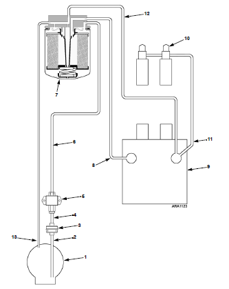
The normal operation of the fuel system is as follows:

  • The electric fuel pump (5) creates a vacuum in the supply line in the fuel tank.
  • Atmospheric pressure in the tank pushes fuel upward (line 6).
  • Fuel reaches the fuel filter and part travels to the mechanical injection pump (9).
  • Fuel is distributed according to the engine sequence to the pistons through the injectors (10).

What to Check with Alarm 20:

If you’re experiencing Alarm 20, it’s likely a fuel system issue. Check the fuel solenoid located at the back of the injection pump.

  1. Fuel Solenoid Issues:
    • Clear alarms.
    • Stand in front of the unit and touch the side or back of the fuel solenoid.
    • Turn on the unit, keeping a finger on the solenoid. The unit should make a starting sound.
    • If the solenoid makes a sound, it’s energized and functioning correctly.
  2. Blocked Fuel System:
    • Inspect the in-line fuel filter located at the inlet hose fitting of the transfer pump.
    • Remove the bolt and washers.
    • Take out the filter from inside the bolt and check for any clogs.
    • Clean the bolt, screen, and fitting.
    • Reinstall the bolt and washers. Replace the screw-on fuel filter if necessary.
  3. Air Presence in the Fuel System:
    • Loosen the manual primer on the transfer pump.
    • Ensure the fuel tank has at least three-quarters of fuel; otherwise, add fuel.
    • Locate the vent fitting on top of the tank near the fuel supply and return lines.
    • Pressurize the fuel tank.
    • Bleed air from the fuel lines.
    • Open the purge bolt on top of the injection pump to release air. If needed, continue pressurizing and priming to remove all air.
  4. Confirming Fuel Return:
    • Locate the return fuel line.
    • Loosen the hose connection and gently pull the line to check for fuel.
    • Lack of fuel indicates an air issue; constant, steady flow confirms a functioning fuel system.

Electrical Issues with Alarm 20:

The starter motor provides the initial impulse to the diesel engine for the first revolutions. Key components include:

  • Starter motor.
  • Starter solenoid.
  • Pinion coupling.

The starter only works during startup, engaging through the coupling solenoid. Once the diesel engine starts turning on its own, the solenoid separates the coupling pinion, disconnecting the starter from the diesel engine.

What to Check for Electrical Issues:

  1. Battery Voltage:
    • Test the battery voltage to ensure it supplies sufficient voltage to the starter motor.
  2. Loose Connections:
    • Check for loose connections that may hinder sufficient current flow to the starter motor.
  3. Starter Solenoid Operation:
    • Visually check the starter solenoid for proper operation. You can observe the coupling to the diesel engine or listen for the characteristic sound.
  4. Diesel Engine Rotation:
    • Ensure the diesel engine rotates enough when using electric start.
  5. Starter Motor Engagement:
    • If the starter engages but doesn’t turn, the issue may lie with the starter motor.

Thermo King Alarm 17.

The Thermo King Alarm 17 indicates that the diesel engine powering the compressor of the refrigeration system failed to start when requested by the microprocessor. The manufacturer provides the following description:

Alarm Code 17:

  • Color Indicator: Yellow
  • Description: The engine did not start.
  • Action: If the unit shuts down, repair immediately. Otherwise, report the alarm at the end of the day.

Troubleshooting Steps:

  1. Check battery voltage; test battery charge to ensure it can retain the charge internally.
  2. Inspect the interface circuit board for fuses and relays, especially fuse F3.
  3. Use a grounding wristband to prevent internal damage due to static electricity.
  4. Place the unit in continuous mode and observe LEDs on the circuit board, particularly LED 25 for the start signal.
  5. Verify for a pushed pin in the circuit 8S connector and check for any open or broken wires.
  6. If equipped with an electric standby motor, check the electric motor clutch for any issues.
  7. Inspect the starter motor’s condition.
  8. Check the relay interface circuit board controlling the fuel cutoff solenoid.

Clearing Alarm Code 17:

  • This alarm must be cleared manually through the keyboard interface screen.

Other Possible Alarms:

  • Alarm 17 may be accompanied by Alarm 84 (Null Restart), but follow the diagnostic procedure for Alarm 17 first.

Programming the Thermoking Microprocessor for Alarm 17 Detection:

  • The microprocessor checks the engine RPM through the engine revolution sensor.
  • If the engine RPM is below 40, Alarm 17 is activated.
  • Additionally, if the engine RPM is above 40 but suddenly drops below 40, Alarm 17 is triggered.

Recognizing Fault 17 in Thermoking:

Fuel System:

  • The electric fuel pump creates a vacuum in the fuel tank supply line.
  • Atmospheric pressure in the fuel tank pushes fuel upward.
  • Fuel reaches the fuel filter and is distributed to the mechanical injection pump and then to injectors.

Fuel Solenoid:

  • When the fuel solenoid is energized, fuel is allowed to pass to the injection pump, enabling the final feed to the injectors.
  • It serves as a cutoff system for shutting down the system.

Starter Motor:

  • The electric starter motor provides the initial impulse to the diesel engine for the first revolutions.
  • Components include the starter motor, starter solenoid, and diesel engine coupling pinion.
  • The starter engages the diesel engine through the coupling solenoid, rotates the diesel engine, and disengages once the diesel engine is running.

Thermo King Alarm 18

The Thermo King Alarm 18 can be described in the following table:

Alarm 18 Thermo King
Yellow. High temperature of the diesel engine coolant.
If the unit shuts down, repair immediately. Otherwise, report the alarm at the end of the day.

The microprocessor utilizes the engine coolant temperature sensor to monitor its temperature. If the coolant temperature rises above an acceptable level, the microprocessor records alarm codes 41 and probably 18. The microprocessor may also shut down the unit.

Fault Code 18 Thermo King:

A high coolant temperature could cause the engine to overheat in a shorter period than usual.

  1. Check for low coolant level or leaks.
  2. Start by inspecting the Thermo King equipment thermostat.
  3. The thermostat may be faulty or covered in dirt; it should be cleaned and checked for recurring errors.
  4. Check if the water pump is functioning correctly.
  5. Pressure wash the radiator if necessary.
  6. A dirty radiator can hinder air circulation, leading to overheating.
  7. Verify if the motor oil is at its usual level.
  8. Check if the oil has its normal consistency; diesel can mix with engine oil in case of leaks.

How the Engine Cools:

The diesel engine cooling system transfers heat generated by combustion and friction to the environment. The system includes engine coolant, propelled by the water pump, driven by the diesel engine.

Once the engine coolant has traversed all spaces and equalized the engine temperature, the mixture of water and coolant significantly increases in temperature. It is then transported to the engine radiator.

The radiator, typically made of aluminum, consists of channels that aid in cooling the liquid flowing through the ducts. Hot water enters the radiator from one reservoir and must pass to the other reservoir through small panel ducts, transferring heat to cooler surroundings. The air from driving passes through the panel on the exterior of the ducts, collecting heat and lowering its temperature.

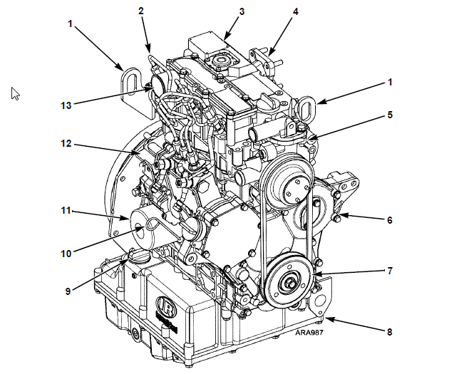
Motor Diesel Thermo King
  1. Support.
  2. Fuel injection line.
  3. Cylinder head cover.
  4. Exhaust manifold.
  5. Water pump.
  6. Gearbox cover.
  7. Crankshaft pulley.
  8. Oil sump.
  9. Oil level switch.
  10. Level rod.
  11. Oil filter.
  12. Fuel injection pump.
  13. Air intake.

What to Do with Alarm 18:

  1. Verify if Alarm 18 is a result of genuine overheating or a false reading.
  2. Diesel engines are designed to operate in a temperature range between 80°C and 100°C. The cooling system’s function is to maintain the temperature within this range for optimal engine performance.
  3. Check the liquid coolant level and eliminate possible leaks.
  4. If the equipment’s thermal load (products) is too high, the cooling circuit pressure increases, causing the diesel engine to exert more effort, leading to overheating.
  5. To check engine overheating, use a thermometer pointing at the thermostat box, at the temperature switch or sensor location, and verify temperature values.
  6. If the temperature is correct, then check the temperature sensor and connections causing the erroneous Alarm 18.
  7. If the engine temperature is indeed high, check the water pump and radiator fan belts.
  8. Verify if the cooling system operating pressure is excessive (some systems or above 7 psi (48 kPa)).
  9. Check the radiator for airflow obstructions or damaged fins.
  10. Check temperatures above and below the thermostat; it should be open at 160 to 190 F [71-88 C].
  11. Verify thermostat operation by checking for a significant temperature differential indicating a stuck-closed thermostat.
  12. Use a thermometer to check temperatures at the radiator inlet and outlet. The differential should be greater than 25 F (14°C).
  13. Clean the radiator if the temperature differential between the inlet and outlet is low.
  14. Rule out internal hose obstructions as they can collapse, causing a restriction while the engine is running. Hoses can also internally degrade, restricting the flow of diesel engine coolant.
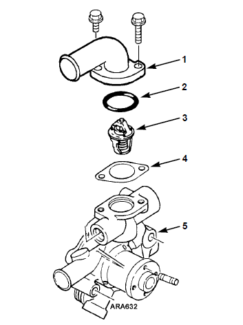
Engine Cooling Thermo King - Water Pump Assembly
  1. Thermostat housing.
  2. Gasket.
  3. Thermostat 180 F (82 C).
  4. Gasket.
  5. Water pump.

Thermo king Code 63

The Thermo King alarm code 63 indicates that the diesel engine powering the refrigeration equipment’s compressor has stopped and is unable to start. The manufacturer provides the following description:

Alarma 63 Thermo King
RojaTake immediate action
Motor Diesel stoppedIf the unit shuts down, repair immediately; otherwise, report the alarm at the end of the day.

Thermo king Code 63 Causes:

The code 63 is a troublesome code as there can be various reasons behind its occurrence. As a first recommendation, check if the fuel filters run out of fuel when this happens and rule out clogged pipes. In most cases, Alarm 63 Thermo King is generated due to fuel-related issues.

Thermo King Fuel System

Common Causes of Engine Blockage (Code 63):

  1. Heat: Excessive heat in the exhaust system, engine, or ambient temperature can vaporize fuel in the lines, causing the engine to stop. The most effective way to address this issue is to let the engine cool. Find shade, park your vehicle, and let the engine rest for a few minutes.

What to do with Code 63 on the Control Panel:

  1. Download and inspect the ServiceWatch data log information.
  2. Review the data using technical user level to determine operating conditions when Code 63 was set.
  3. Use the service test mode in operation to replicate operating conditions as needed.
  4. Operating data can be viewed in technical mode.
  5. Perform a pre-trip test to determine the cause of the shutdown.
  6. Check for other alarm codes and proceed as indicated for each code.

How to Physically Address Code 63:

  1. Check the fuel level and verify the proper operation of the fuel pump.
  2. Inspect the air filter and intake hose for obstructions.

Electrical Checks to Overcome Code 63:

  1. Verify unit fuses.
  2. Check if the RPM sensor is functioning correctly.
  3. Review operation relay and fuel solenoid components and circuits.
  4. Check for low battery voltage.
  5. Ensure all ground connections on the master ground plate are secure.
  6. Check for a seized compressor or motor.

Fuel Solenoid and Code 63:

When the fuel solenoid is energized, it allows fuel to flow to the injection pump, providing the final feed to the injectors. This system acts as a cutoff system to allow system shutdown.

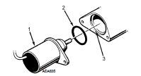
Thermo King Fuel Solenoid Thermo King Fuel Solenoid
  • Check for power at the fuel cutoff solenoid with the ignition on and the engine cranking. If there’s no power, ensure to test all fuses and relays.
  • Inspect the wiring of the fuel cutoff solenoid for damage.

Typical Values for Fuel Solenoid:

Solenoide de Combustible a 12.5 voltios corriente continua.Valores tipicos de resistenciaValores tipicos de amperaje
Bobina de Puesta en Trabajo35 a 450.2 a 0.3
Bobina de Mantenimiento0.524 a 29

Electrical Verification for Overcoming Code 63:

  1. Verify unit fuses.
  2. Check if the RPM sensor is functioning correctly.
  3. Review operation relay and fuel solenoid components and circuits.
  4. Check for low battery voltage.
  5. Ensure all ground connections on the master ground plate are secure.
  6. Check for a seized compressor or motor.

Failure and Alarm 63 Thermo King:

The starter motor is responsible for giving the initial impulse to the diesel engine so that it can develop its first revolutions.

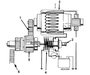
Components of the Starter Motor:

  1. Pinion Gear
  2. Starter Motor
  3. Plunger
  4. Starter Solenoid
  5. Pinion Assembly
  6. Ring Gear

Starter Motor Operation:

  • When energized, the starter motor couples to the diesel engine through the engagement solenoid.
  • For the starter motor to begin turning, it must be engaged.
  • If the starter solenoid is correct, engagement occurs, and the starter motor turns the diesel to start.

This coupling involves joining (meshing) the pinion assembly (5) to the ring gear (6). Once the diesel engine starts turning on its own, the solenoid disengages the coupling, disconnecting the starter motor.

Starter Motor Starter Motor – Thermo King

These steps should help you troubleshoot and address Thermo King Alarm Code 63 effectively. Always refer to the manufacturer’s documentation for specific details and instructions related to your equipment.

Thermo King alarm code 14.

The Thermo King alarm code 14 indicates that the unit has exceeded the defrost time during the defrost cycle.

The defrost cycle is a process that melts the ice and frost that accumulates on the evaporator coil. This ice and frost can block airflow, reducing the unit’s efficiency.

The alarm 14 Thermo King can be described in the following table:

Alarma 14 Thermo king
Verde = OKDefrosting completed on time
Report the alarm at the end of the day.

Why does Thermo King code 14 occur?

This error typically occurs when the defrost time is excessively prolonged. In many Thermoking units, electric defrost has a time limit of 90 minutes with a power supply voltage higher than 440 VAC and 120 minutes below 440 VAC.

The electric heating signal is on for too long when:

  • There is low voltage from the power source.
  • Defective heating elements.
  • Evaporator fans are operating during defrost.
  • Evaporator sensor is incorrectly placed.
  • Evaporator compartment temperature is very low, even under normal operating conditions.

What to do with code 14:

  1. Initiate a manual defrost and check the amperage flow and evaporator coil temperature.
  2. Evaluate the defrost performance.
  3. Open the evaporator door and verify the location of the evaporator coil sensor.
  4. It’s crucial to address the underlying issues causing the extended defrost time to ensure proper functionality and prevent further occurrences of alarm code 14