Compressor starts but the air conditioner does not cool.

In this post, we delve into various reasons why a compressor may start, but the air conditioning unit doesn’t cool effectively. These causes and their potential solutions are as follows:

  1. Faulty Compressor: One of the most critical issues is a compressor that fails to adequately circulate refrigerant gas. This becomes noticeable when the pressure gauge remains unchanged. For instance, when the compressor starts, the low-pressure gauge needle should drop, while the high-pressure gauge needle should rise. Additionally, when the compressor can’t compress properly, the amperage remains unusually low. In such cases, the recommended solution is to replace the compressor.
  2. Refrigerant Leak: A recent refrigerant gas leak can cause the compressor to operate, but the unit fails to cool properly. To address this, it’s crucial to check the refrigerant pressure. Moreover, when refrigerant levels are low, the amperage or current consumed by the compressor drops below the normal range. To remedy this, search for and repair the leak, look for oil stains as indicators, and use soapy water to identify bubbles. Be particularly suspicious of any connections.
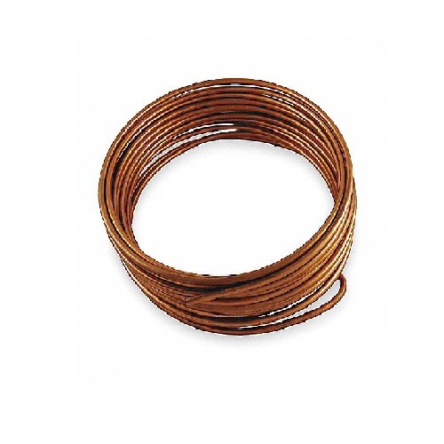
  3. Obstruction in the Refrigeration System: External obstructions in the air conditioning filter will result in reduced airflow. If the obstruction is internal, such as in the capillary tube, it restricts the flow of refrigerant within the system. In both scenarios, the compressor can operate, but cooling is inadequate. To address this issue, clean the evaporator coil and its air filter, and clean or replace the capillary tube as needed.
  4. Condensation Issues: Inadequate condensation of the refrigerant at the outlet of the external coil can be attributed to a deteriorated, clogged, or dirty coil. This situation leads to excessively high pressure and reduced equipment performance. It is necessary to either clean the external condenser coil or perform internal cleaning, depending on the specific circumstances. When condensation is problematic, the compressor’s electrical consumption tends to be higher than normal.
  5. Obstruction of the Air Conditioning Turbine: When the air conditioning turbine is obstructed, it can result in significant moisture accumulation on the coil and insufficient airflow. Proper maintenance of the turbine and the evaporator is essential to resolve this issue.
  6. Fan-Related Problems: If one of the fans, whether it’s the condenser fan or the evaporator fan, stops or operates at a slower speed than normal, the unit might experience inadequate pressure. This can lead to diminished performance or evaporator freezing. It is recommended to check the fan capacitor and bearings. In cases of serious faults, the fan should be replaced.
  7. Temperature Sensor Issues: If there are problems with temperature sensors, it can lead to evaporator freezing and reduced airflow. In such instances, it’s important to check the temperature sensors.

These considerations help address the common issues associated with a running compressor that doesn’t result in effective cooling in an air conditioning system.

What to do when the amperage of the A/C is lower than normal?

In this instance, I will talk to you about a potential issue that an air conditioner may face when the amperage is lower than normal, meaning the current of the unit is less than the equipment’s nameplate value.

Let’s consider a hypothetical example of an air conditioning unit that should consume 4.6 amperes. If the amperage is only slightly lower, for example, 4 amperes or 3.9 amperes, we can say that the compressor is working well and cooling properly. In this case, there should be no cause for concern.

If the amperage is significantly lower, such as 2.9 amperes, 2.8 amperes, or even 2.7 amperes, this indicates another issue. It could be due to a dirty air filter or a dirty indoor unit coil, which restricts the airflow and reduces the pressure in the system, resulting in lower amperage. In this case, it is recommended to perform maintenance to clean the coil.

Check the speed of the fan blade; if it’s slow, inspect the fan capacitor.

Another cause could be an obstruction in the air turbine, preventing proper airflow through the coil. This can also result in lower amperage and may lead to the unit freezing up.

Furthermore, the lack of refrigerant or insufficient refrigerant charge can lead to lower amperage. This can be verified by measuring the refrigerant pressure and comparing it with the recommended values for the unit.

If, on the other hand, the amperage is extremely low, such as 0.9 amperes or 1 ampere, this may indicate that the compressor is not compressing correctly. There could be a complete lack of refrigerant in the system or a mechanical failure in the compressor.

When the amperage is very low, and the refrigerant pressure does not rise when the unit is turned on, it is likely that the compressor is not compressing the refrigerant or circulating properly. In this case, the solution may be to replace the compressor.

Remember that on cooler days or in locations with lower thermal loads, such as places with fewer occupants, it is normal for the power consumption to be lower than usual, although not significantly below the rated value.

Error Code E6 in Air Conditioning

Error code E6 can be grouped for different air conditioning manufacturers into several groups based on their similar meanings:

Group 1 – Ambient Temperature Sensor or Evaporator Issues In this group, we can group the following air conditioning brands:

  • General Electric
  • Midea Air Conditioning
  • SAMSUNG
  • York Central Air Conditioning
  • FUJITSU
  • PANASONIC

Now, let’s begin with some basic definitions.

What is the Temperature Sensor? The temperature sensor is a device that measures the room air temperature in the case of the ambient sensor and the evaporator temperature in the case of the freeze sensor. It is located in the indoor unit of the air conditioner.

The temperature sensor is an electrical resistance that receives electrical current from the control card or board. The electrical resistance of the sensor changes when the temperature changes, causing a voltage change in the electrical current supplied by the electronic card. This voltage change is detected by the card or electronic board. The sensor sends this signal to the card or electronic board. The card or electronic board uses this information to adjust the cooling or heating power.

In very rare cases, the error may be caused by a damaged electronic board. The electronic board controls the operation of the air conditioner. If the board is damaged, it can cause problems with the interior ambient temperature sensor.

Group 2 – Communication Problems between Indoor and Outdoor Units In this group, we can group the following air conditioning brands:

  • BOSH
  • DAEWOO
  • TRANE
  • GREE
  • ELECTROLUX
  • SHARP
  • KELVINATOR

The failure of communication between the evaporator and condenser is the most common error in mini-split inverter systems. Follow these steps:

  1. Verify that the control card of the external unit or condenser is indeed receiving voltage. If the installation is in good condition, the voltage should not fluctuate, and if it does, it should not exceed 3% of the nominal voltage. In other words, if the equipment is rated at 220V, the voltage at the terminals of the external unit or condenser should not drop by more than 5 volts. If this is not the case, there are electrical installation problems that need to be checked.
  2. If the power at the terminals is within normal values, the next step is to check if the control board of the condenser is turning on. Many external boards come with indicator LEDs; you can check if any of them are lighting up. This allows us to infer that at least voltage is reaching the board. If you don’t see any indicator lights on or blinking, it’s likely that the error is due to a fault in the external board. However, we must make sure that the control board does have indicator lights or that these are at least visible without disassembling the board.
  3. If, indeed, you manage to see the indicator lights, you would need to check the condition of the connection terminals of the external unit. If there is any rusty screw or sulfated terminal, you should replace it immediately and test if this resolves the issue.
  4. If the issue persists, you should install a temporary communication cable, only on the signal line, as they call it, which is one of the three wires that the wiring connecting the internal and external units carries. This can be a single-strand telephone wire without splices. If, during testing, you find that the equipment starts operating normally, it means you have a problem with the wiring, and you should replace it entirely, making sure it has no splices.
  5. If this does not resolve the issue, you would be facing a problem with one of the control boards, either the internal or the external one. In some cases, both can have faults. The communication error may also appear after the equipment has been operating normally for a few hours or even days. In any case, you should follow the previous steps.

Group 3 – Compressor Startup Problem This error code meaning is associated with the DAIKIN brand. Depending on the type of compressor, check in conventional models, the working capacitor of the compressor.

Group 4 – Pressure Value Problems This error code meaning is associated with the HAIER brand. Check for maintenance or cleaning of the condenser and evaporator to rule out overpressure or low values due to poor thermal exchange in these parts.

18000 BTU Power Consumption

Calculating how much an 18,000 BTU air conditioner consumes is essential for air conditioning specialists to assess the performance of the installed system. Additionally, the amperage information helps users understand the energy consumption of the equipment, whether to evaluate purchase options or verify electricity bills.

How many watts does a 18000 btu air conditioner use?

The consumption of an air conditioner depends on various factors, including the efficiency of the air conditioner, the thermal load inside the space, the outdoor temperature, and the time that has passed since the equipment was turned on for the first time.

To start, it’s important to know the SEER (Seasonal Energy Efficiency Ratio) parameter of the air conditioning unit, as it measures the equipment’s performance. With the SEER parameter, you can estimate the average electrical power consumed by the air conditioner in watts (W). Note that for non-inverter air conditioners, a SEER value of less than 12 is considered inefficient.

Here’s a table showing the average electrical power consumption based on SEER for a 18000 BTU/h air conditioner:

SEER Average
Power (W)
101800
111636.4
121500
131384.6
141285.7
151200
161125
171058.8
181000
19947.4
20900

How much electricity does a 18,000 btu air conditioner use per hour?

To find the amperage consumption, you can use the power consumption value from the previous table and refer to the following tables based on the type of supply voltage. Here are some sample values:

How many amps does a 18000 btu air conditioner use?

For a single-phase power supply (PH1):

Power (W)110 V115 V120 V127 V220 V230 V240 V
90011.36 A10.87 A10.42 A9.84 A5.68 A5.43 A5.21 A
95011.99 A11.47 A11.00 A10.39 A6.00 A5.74 A5.50 A
100012.63 A12.08 A11.57 A10.94 A6.31 A6.04 A5.79 A

For a three-phase power supply (PH3):

Power (W)220 V230 V240 V380 V400 V440 V
9003.28 A3.14 A3.01 A1.90 A1.81 A1.64 A
9503.47 A3.32 A3.18 A2.01 A1.91 A1.73 A
10003.65 A3.49 A3.35 A2.11 A2.01 A1.82 A

How much power does a 18000 btu air conditioner use?

For example, for an 18,000 BTU/h air conditioner with a SEER of 12, you can expect an average power consumption of 1,500 watts and an average current consumption of approximately 9.47 amperes.

Understanding the amperage and power consumption of your air conditioner can help you make informed decisions about its usage and energy costs.

Error Code E3 Air Conditioning

We will explain error E3 in various air conditioning brands.

Let’s begin by saying that error E3 can indicate a fault in the indoor unit’s fan or blower, located inside the premises. This cause is applicable to the following air conditioning brands:

  • Carrier
  • General Electric
  • Midea
  • Samsung
  • York
  • Olimpia Splendid
  • Bosch
  • Daewoo
  • Westinghouse

To resolve issues with the indoor unit’s fan, it is recommended to:

a. Check the condition of the capacitor, as a faulty capacitor can result in slow fan speed.

b. Inspect for unusual noises when rotating the blower’s turbine or any obstructions, which may arise from blower bearing problems.

c. There might be issues with the fan speed sensor, often an effect hall sensor.

d. Verify the fan power connections and the current supply relay.

Now, the meaning of error E3 can be different.

The cause of error E3 may be a lack of refrigerant gas or very low gas pressure. In this case, it is necessary to check for a leak. The brands associated with this meaning are:

  • Trane
  • Gree
  • Haier
  • Electrolux
  • Sharp
  • Kelvinator

When the air conditioning unit is lacking refrigerant gas, its electrical current consumption is lower than normal. You can use an ammeter clamp to confirm the presence of the issue.

Visually, you can observe oil stains on pipes, connections, indoor and outdoor units, resulting from the leak.

For the Trotec brand, error E3 is due to an issue with the evaporator temperature sensor.

For problems with the temperature sensor, it is recommended to disconnect it and measure its resistance using a multimeter. Its value should match the one indicated in the manual and should never be infinite.

For the Fujitsu brand, error E3 can be related to a short circuit in the local air temperature sensor.

For the Toshiba brand, Error E03 occurs when there is a connection error between the indoor unit and the control panel.

For the brands Mitsubishi Electric and Panasonic, error E3 indicates a communication problem with the remote control. No control signal is being emitted.

For Daikin, error E3 probably originates when the high-pressure switch is activated due to excessive pressure or a power failure that affects the transformer, causing the sensor signals not to be interpreted.

What does e4 mean on an air conditioner?

We will explain error E4 in various air conditioning brands.

Error e4 Air Conditioner:

Let’s begin by stating that error E4 can indicate issues with a temperature sensor in the air conditioning unit. These sensors are primarily NTC-type electrical resistors, with their resistance decreasing as temperature rises. The control board responsible for this regularly provides a voltage, typically around 5 volts, which varies with resistance.

The affected brands and their specific issues are as follows:

  • Carrier: Problems may include an open circuit or a short circuit in the ambient temperature sensor, whether it’s located indoors or outdoors, depending on the unit’s model.
  • Midea: The problem often involves the outdoor unit’s temperature sensor.
  • York: Issues may arise with the indoor ambient temperature sensor, especially in central York air conditioning units, where the temperature sensor in the compressor discharge tube can be problematic.
  • Bosch, Westinghouse, Fujitsu: Error E4 typically relates to problems with the indoor ambient temperature sensor, such as an open circuit or a short circuit.
  • Trane, Gree, Sharp, Electrolux, Kelvinator: Error E4 serves as a protection mechanism against high compressor exhaust temperatures.
  • Haier (indoor unit): Error E4 indicates an incorrect EEPROM. In portable Haier air conditioners, it signifies the unit has a built-in tank that requires periodic emptying.

To assess the temperature sensor, use a multimeter set to the kilohm scale. Disconnect the sensor and measure its resistance, which should decrease when you touch it. The sensor should not display infinite or zero resistance; its value should be cross-referenced with the manufacturer’s catalog.

Additionally, check if the control board supplies the sensor with the correct voltage. With the sensor connected, the multimeter should read approximately 2.5 volts in the DC voltage scale, as depicted in the figure.

In the case of Daikin, error E4 is attributed to the activation of the low-pressure switch (LBS), indicating a detected lack of liquid or gas pressure in the air conditioning system.

For Samsung, error E4 can be linked to forced defrosting, low refrigerant gas levels, a malfunctioning pump, a damaged temperature sensor, or variations in system pressure. Refrigerant leaks result in reduced pressure, detectable using an ammeter clamp since the air conditioner’s electricity consumption decreases in the presence of a refrigerant gas leak. Furthermore, you can visually inspect for oil stains on both the outdoor and indoor units and pipes, as refrigerant leaks leave traces of lubricant.

Capillary for a 1/4 HP compressor

The size of the capillary for a 1/4 HP compressor primarily depends on the type of refrigerant gas used and the temperature of the evaporator in the application

The best way to select a capillary is not to use the HP of the compressor motor as a reference. Instead, it is advisable to consider the cooling capacity of the compressor, which is typically measured in Btu/h and Kcal/h.

However, there are cases where the cooling power data for compressors may not be available, and in such situations, we still need to determine the size of the capillary tube.

The issue with using 1/4 HP as a reference is that it is an electrical parameter, which introduces the motor’s efficiency factor into the equation, while disregarding the efficiency of the compressor itself.

For the selection of the capillaries the following reference is taken into account:


Condensing

 temperature
_
LBP
Low
Pressure
-23,3 °C
-10°F
54,4 °C
130°F
MBP
Medium
Pressure
-6,7 °C
20°F
54,4 °C
130°F
HBP
High
Pressure
7,2 °C
45°F
54,4 °C
130°F
Source: Tecumseh

Capillary measure for 1/4 compressor Rules:

  • Capillary tubes depend on both their length and diameter to determine their overall restriction.
  • A percentage change in diameter can affect the flow more significantly than an equivalent change in length.
  • The restriction can also be adjusted by either lengthening or shortening the tube.
  • As a general rule, the longer the tube, the slower the flow. However, there comes a point where excessively increasing the tube’s length to enhance restriction and reduce flow becomes inefficient and often futile.
  • Conversely, as the tube’s length decreases, the flow gradually increases until it reaches a critical point, where the flow rate starts to increase more rapidly with each further reduction in length.
  • If the length is further reduced, it reaches a stage where even minor alterations in length result in significant increases in flow.
  • At this point, the tube behaves less like a capillary tube and more like an orifice.
  • As a practical recommendation, it’s advisable to keep the tube length within a range of no less than 5 feet and no more than 16 feet.
  • While exceptions may exist, adhering to this guideline for daily operations will help minimize many potential issues.”

What capillary does a 1/4 HP compressor have with R134a?

diameter
in
length
m
HBP0.0421.8
MBP0.0422.0
Source: Tecumseh

Capillary for 1/4 HP motor with R-410A?

T= -10°F
-23.3°C
Diameter/
length
T= 25°F
-3.89°C
Diameter/
length
T= 45°F
7.2°C
Diameter/
length
0.031 in 73″0.031 in 40″0.042 in 101″
Source: JB Industries

What capillary does a 1/4 compressor use for R404A?

PowerConditionDiameter and
Length
1/4 HPEvaporation temperature =-23°C
ONLY When the compressor reaches a
cooling capacity of 1000 Btu/h
0.031″ – 4½ ft
1/4 HPEvaporation temperature =-6.7°C
ONLY When the compressor reaches a
cooling capacity of 1000 3000 Btu/h
0.052″ – 8½ ft

Table of capillary tube compressor 1/4 HP for R22

HPdiameter
in
length 
m 
1/4HBP0.0503.0
1/4MBP0.0362.5
Source: Tecumseh

Table of Capillary Tube R407C Compressor 1/4HP:

Low
Temperature
Diameter in
Length in
Average
Temperature
Diameter in
Length in
High
Temperature
Diameter in
Length in
0.031 56″0.031 31″0.042 79″

Capillary Tube for 1/3 HP

The capillary tube for a 1/3 HP refrigerator depends on the type of refrigerant gas used and the application’s temperature, both in the evaporator and condenser.

ATTENTION: At the end of this article, you can access a FREE course on capillary tubes for refrigerant gases.

The capillary tube for a refrigerator can regulate the passage of refrigerant because it has a very small diameter, which restricts the flow of the fluid, and it is also relatively long, contributing to the pressure loss of the flow that passes through it.

1/3 HP Refrigerator Capillary Tube:

The following video prepared by CST explains some recommendations to take into account before definitively selecting the size of a capillary tube.

Capillary for 1/3 hp compressor in refrigeration:

Applications
according to
Temperature

evaporation temperature
_

Condensing temperature
_
LBP
Low Pressure
-23,3 °C
-10°F
54,4 °C
130°F
MBP
Medium Pressure
-6,7 °C
20°F
54,4 °C
130°F
HBP
High Pressure
7,2 °C
45°F
54,4 °C
130°F
Source: Tecumseh

Capillary for 1/3 motor for cooling:

Before selecting the capillary for 1/3 HP motor you should know:

  • Capillary tubes depend on both their length and diameter to determine their overall restriction.
  • A percentage change in diameter can affect the flow more significantly than an equivalent change in length.
  • The restriction can also be adjusted by either lengthening or shortening the tube.
  • As a general rule, the longer the tube, the slower the flow. However, there comes a point where excessively increasing the tube’s length to enhance restriction and reduce flow becomes inefficient and often futile.
  • Conversely, as the tube’s length decreases, the flow gradually increases until it reaches a critical point, where the flow rate starts to increase more rapidly with each further reduction in length. If the length is further reduced, it reaches a stage where even minor alterations in length result in significant increases in flow.
  • At this point, the tube behaves less like a capillary tube and more like an orifice.
  • As a practical recommendation, it’s advisable to keep the tube length within a range of no less than 5 feet and no more than 16 feet.
  • While exceptions may exist, adhering to this guideline for daily operations will help minimize many potential issues.

What capillary does a 1/3 compressor use with R134a?

HP Compressor
Electric Power
Applicationdiameter
in
Length
m
1/3LBP0.0362.5
1/3HBP0.0502.0
1/3MBP0.0423.0
1/3HBP0.0501.5
1/3MBP0.0421.5
Source: Tecumseh

What capillary does a 1/3 compressor have with R-410A?


HP power
Low
Evaporator 

Temperature -10°F 
Diameter/ Length


Average Evaporator 

Temperature
25°F
Diameter/
Length

High Evaporator 

Temperature
45°F
Diameter/
Length
1/30.031 in 38″0.031 in 30″0.042 in 62″
Source: JB Industries

Capillaries for 1/3 HP Compressor with R404A:

For an electrical power of 1/3 HP, a cooling capacity close to 1100 Btu/hour is expected with the following dimensions:

Refrigeration 
Capacity
Diameter/ 

Capillary
Length
Evaporator
temperature 

-10 °F
-17.22 C
Temperatura
Evaporador
25°F

-3.89°C
Temperatura
Evaporador
45°F

7°C
1000 Btu/h
250 Kcal/h
0.031″ – 4½ ft0.031″ – 5 ft0.031″ – 5 ft
1,250 Btu/h
312 Kcal/h
0.040″ – 12 ft0.040″ – 13 ft0.040″ – 13½ ft

Capillaries for 1/3 HP Compressor with R22

HP
Compressor 

Power
Applicationdiameter
in
Length
m
1/3HBP0.0502.0
1/3MBP0.0423.0
Source: Tecumseh

R407C Capillary Tube Table:

The following table shows the approximate values ​​of the diameter and length of the capillary, depending on the evaporator temperature, and the power in HP of the compressor.

HPLow
Temperature
Diameter

in
Length

in
Average
Temperature
Diameter in
Length in
High
Temperature
Diameter in
Length in
1/30.031 30″0.042 96″0.042 47″

What is the refrigeration capacity of a 1/3 HP compressor when used with its corresponding capillary?

The refrigeration capacity will depend on the evaporation temperature:

-35°C-30°C-25°C-20°C-15°C-10°C
388,47
BTU /H
592,99
BTU /H
830,55
BTU /H
1108,75
BTU /H
1435,18
BTU /H
1817,44
BTU /H

1/3 HP Compressor Cooling Capacity Chart

With the values ​​in the table, a compressor with a 1/3 HP motor that works at a temperature of -20°C and R134a gas achieves a cooling capacity close to 1108.75 Btu/hour.

HOWEVER, you should be aware that the cooling capacity of the 1/3 HP compressor may be different with varying operating conditions such as:

  • Compression Process Type.
  • Compressor performance.
  • Hertz Frequency Change.
  • Compressor motor rpm.
  • Temperature of the external area of ​​the condenser.
  • Condenser exchanger cooling method (natural or forced)
  • Degree of subcooling of the refrigerant gas reached in the condenser.
  • Degree of superheating of the refrigerant at the outlet of the evaporator.

The reference for this table are:

  • Degree of superheat at the outlet of the evaporator of 5°C
  • Subcooling value at the condenser outlet of 5 °C
  • 35°C ambient temperature
  • Reference refrigerant R134a.

When any of these references vary, then the refrigeration capacity of the 1/3 HP compressor will be different.

Refrigeration Compressor Starting Torque (HST):

When it comes to refrigeration compressors, the term HST holds significance. HST, which stands for High Starting Torque, refers to a specific characteristic of the compressor’s motor.

In simpler terms, an HST compressor possesses a motor designed to deliver a powerful starting torque. This trait holds crucial importance for the compressor’s functionality.

HST compressors are unique in that they can effectively accommodate both capillary tubes and thermostatic expansion valves as expansion elements. Unlike some other compressors, HST units display a remarkable ability to achieve equilibrium between low and high pressures promptly once the equipment is deactivated, in the case of capillary tube systems.

In contrast, systems utilizing a thermostatic expansion valve exhibit a slower pressure balance restoration after shutdown. This can present a challenge during the subsequent startup of the compressor’s motor.

Illustrated in the accompanying graph are the distinctive performance curves of a High Starting Torque (HST) compressor, providing a clear comparison against compressors with lower starting torque. The tabulated data reveals that HST compressors require a start capacitor for proper operation.

HST compressors are associated with two types of motors: C S R and C S R I. These motors are equipped with an induction design and incorporate a start capacitor. Notably, the C S R motor includes a relay to govern the actions of the start capacitor.

The functionality of the relay is crucial in HST compressors, particularly those employing a voltmeter relay with normally closed contacts. The relay coil operates in parallel with the compressor’s start coil. As the motor-compressor’s speed increases, the voltage in the start coil rises until it reaches a specific threshold. At this point, the relay’s armature is engaged, leading to the disconnection of the start capacitor from the circuit. This action ensures the continued operation of the compressor without interference.

It’s worth noting that the HST compressor’s motor configuration extends to the C S I R type motor as well. While similar to the C S R motor, the C S I R motor lacks a run capacitor, providing a streamlined design.

In summary, the HST compressor’s unique motor design and high starting torque capability make it a versatile and essential component in refrigeration systems. Whether paired with a capillary tube or a thermostatic expansion valve, the HST compressor ensures efficient performance and reliable startup, bolstered by its intricate motor configuration.

Can the GAS R290 be mixed with the REFRIGERANT R600A?

SPECIFICALLY, we are going to study what happens when R600A gas is added to a system that originally uses R290 refrigerant, resulting in a mixture of refrigerants within the system.

https://youtu.be/Fr1zFseYdFo

Let’s start by saying that although the equipment can cool, it is not recommended to mix these gases because it alters the operation points of the refrigeration cycle. However, we will explore everything that can happen when the mixture is performed so that the concepts become clear.

Remember that both gases are compatible with mineral oil, POE oil, and alkylbenzene.

After a proportion of more than 50% of R600A, as the amount of R600A refrigerant in the mixture increases, the coefficient of performance of the system (COP) decreases, meaning the system becomes less efficient.

On the screen, we have different performance values for some mixtures between R600A and R290.

As the amount of R600A increases in the mixture, with values well above 50% of R600A, the cooling capacity or refrigeration power of the system starts to decrease. In other words, it takes more time to cool down or has the ability to cool down fewer products.

On the screen, we have different cooling power values for some mixtures between R600A and R290.

The greater the amount of R290 in the mixture, without exceeding 50% concentration, the compressor discharge temperature decreases. After surpassing 50%, the opposite occurs. Remember that a lower compressor discharge temperature increases the lifespan of the motor windings.

On the screen, we have different discharge temperature values for some mixtures between R600A and R290.

Before the 50% proportion of R600A in the mixture, as the amount of R600A increases, the mass flow rate of refrigerant in the equipment increases, along with the need for other capillary tube measures.

On the screen, we have different mass flow rate values for some mixtures between R600A and R290.

Experimentally, it has been demonstrated that the optimal efficiency point for the mixture of R600A and R290 is when each gas contributes 50% by mass to the mixture.