Graduated from the University of Carabobo in Venezuela. (1996-2001).
Credential of the College of Engineers of Venezuela Number 131,187.
Specialist in the area of Industrial Refrigeration and HVAC Systems.
This series is made up of the RCUF45AZPY1 RCUF50AZPY1 RCUF60AZPY1 models with capacities of 160, 178, 215 KW. These chillers work with R-134a with an electronic expansion valve, with a semi-hermetic screw compressor.
Hitachi V Series Chiller:
The V series uses the DC inverter type scroll compressor, which encompasses 25% to 100% capacity control, allowing precise matching of building loads, and reducing energy input. unit, uses R410a refrigerant
Water Cooled Hitachi Chiller:
Chiller Hitachi WZPY Series
This series is made up of the RCUF50WZPY RCUF65WZPY RCUF80WZPY models, with a capacity of 190, 238, 298 KW, which works with a screw compressor with R-134a refrigerant.
Chiller Hitachi Direct-drive with VSD:
This series of chillers is designed for capacities between 300 and 1100 tons of refrigeration, with a centrifugal compressor. It is identified with the acronym HC-F_D_GFVG HC-F_D_GXVG with two-stage compressor, frequency inverter and economizer.
Chiller Hitachi Inverter GXG-SIT / GSG-SIT
This series that works with a centrifugal compressor, is made up of the HC-F300GSG-SIT models for capacities between 200 and 300 TRF, HC-F350GSG-SIT for capacities between 301 and 350 TRF, HC-F400GSG-SIT for capacities between 351 and 400 TRF.
Where to learn all about chillers?
We have prepared a complete training in chilled water installations with chillers.
It is a series of chillers for a capacity range between 43.9 and 129KW, it works with a fixed speed compressor plus an inverter scroll type compressor, variable speed condenser fans.
Mitsubishi NX2 2 Cooler:
It is a series of air-cooled condenser chillers, with two scroll-type compressors with a single refrigeration circuit, to cover a range of capacities between 40kW and 221kW. Available in R410A or R454B refrigerant. Used for comfort applications.
Mitsubishi NX2 4 Cooler
It is a series of chillers, with air-cooled condenser to cover a range of capacities between 168kW to 366kW. They are teams consisting of two refrigeration circuits, for a total of 4 scroll-type compressors. Available in R410A or R454B refrigerant. Used for comfort applications.
Mitsubishi EACV / EAHV E Series Cooler:
The e-series chillers allow up to six individual units to be connected together, for a system capacity of 90 kW to 1,080 kW. Available as a cooling only or heat pump version, it works with an inverter scroll compressor with R-32 refrigerant.
Where to learn all about chillers?
We have prepared a complete training in chilled water installations with chillers.
It is an air-cooled condenser chiller, turbocharged with variable frequency drive, multiple compressor design (up to 8 parallel), and completely oil-free Open-Flash economizers.
Chiller Engie QUANTUM X:
To operate in a capacity range of 300 to 3000 kW with water-cooled condenser, optionally with R-513A or R-134a
Chiller Engie QUANTUM G:
It is a chiller with a water-cooled condenser, which uses the ecological refrigerant R-1234ze for a capacity range between 200 and 3000 kW.
Chiller Engie QUANTUM W:
It is a water-cooled condenser chiller, Turbocharged with frequency converter, Open-Flash economizers and completely oil-free machine design are components.
The operating range is smaller than with QUANTUM X, the cooling capacity and energy efficiency are better. For thermal loads of about 900KW.
Chiller Engie QUANTUM GA:
It is an air-cooled condenser chiller with a capacity range of 300 to 1,400 kW. It works with R-1234ze, with a GWP less than 1.
Chiller Engie QUANTUM GS
The QUANTUM GS is a variant of the QUANTUM S that is operated with the environmentally friendly refrigerant R-1234ze.
The QUANTUM GS can be divided, when required, into an indoor machine unit. Covers a capacity range from 300 to 2000 kW.
Chiller Engie QUANTUM MARENUM:
The QUANTUM MARENUM Chiller is seaworthy and available in many variants, tailored to individual applications: for ferries, freighters or yachts, and even for use on non-civil ships. With water-cooled condenser, and its cooling capacity starts at 300 kW,
Where to learn all about chillers?
We have prepared a complete training in chilled water installations with chillers.
It is a series with variable speed screw compressor and air cooled condenser with ECM fans, available from 100 to 565 tons. With variable volume ratio compressor technology, it senses the precise amount of lift needed and adjusts the compression ratio on the fly to deliver optimal efficiency, regardless of ambient temperature.
Chiller Daikin Trailblazer:
It is a series of chillers with an air-cooled scroll compressor, with a capacity range between 10 and 240 tons refrigeration, it has a heat recovery system, optional factory installed that allows you to use up to 45% of the heat that normally the condenser is rejected for preheating and dehumidification.
Daikin chiller with water-cooled condenser.
Chiller Daikin Magnitude:
It is a centrifugal compressor chiller with direct drive technology, integral variable frequency drives and R134a refrigerant that does not damage ozone. With available capacities from 75 to 1500 tonnes of refrigeration, the Daikin Magnitude centrifugal cooler offers the most complete size range of oil-free magnetic bearing coolers.
Chiller Daikin Navigator:
It is a series of water-cooled screw compressor chillers, handling capacities from 120 to 300 tons refrigeration. They are designed as a fully VFD-driven platform, integrating Variable Volume Ratio (VVR) compressor technology to give you the advantage of a quiet system, adapting to real-time demands for the most efficient and efficient operation. economical possible.
Daikin single compressor chiller:
It is a series of chillers with a centrifugal compressor, with a capacity of 300 to 1800 tons of refrigeration, that work with R-134a refrigerant.
Where to learn all about chillers?
We have prepared a complete training in chilled water installations with chillers.
This Series offers capacities from 150 to 300 tons refrigeration, works with screw compressor, with permanent magnet variable speed motors, and a combination of excellent efficiency at part load and full load.
Chiller Trane CGAM:
It is a series of chillers, which works with scroll compressors, in a capacity range from 20 to 130 tons of refrigeration. It works with a reduced charge of HFC-410A refrigerant.
Chiller Trane RTAC:
It is a series of chillers with screw compressor, to operate in a range of capacities between 140 and 500 tons refrigeration, that work with R-134a.
Trane chiller with water cooled condenser:
Trane CenTraVac EarthWise Chiller:
It is a series of chillers with a centrifugal compressor, to operate with capacities between 120 and 2000 tons refrigeration.
Chiller Trane CenTraVAC Series S:
This series is designed to operate in a range of 180 to 390 tons refrigeration. It works with an oil-free centrifugal compressor.
Chiller Trane CenTraVAC Series L:
This series is designed to operate in a range of capacities between 400 and 1800 tons refrigeration. Optimized for industrial process cooling, and data center equipment. To supply chilled water from 60 ° F to 70 ° F more efficiently.
Chiller Trane CenTraVac Duplex:
Designed to work in a capacity range between 1500 and 4000 tons refrigeration. Designed for high capacity applications, it consists of two separate centrifugal compressors with independent refrigerant circuits.
Where to learn all about chillers?
We have prepared a complete training in chilled water installations with chillers.
Chiller York YCAL: It is a series of chillers with scroll compressor, which works with R-410A refrigerant, for a capacity range between 15 and 35 Tons of refrigeration.
Chiller York YLAA: It is a series of chillers with a scroll compressor with a variable frequency drive, which works with R-410A refrigerant, for a capacity range between 40 and 230 Tons of refrigeration.
Chiller York YVAA: It is a series of chillers with a screw compressor with variable frequency drive, which works with R-410A, for a capacity range between 150 and 575 Tons of refrigeration.
Chiller York YVFA: It is a series of chillers with screw compressor with variable frequency drive, which works with R-410A refrigerant, for a capacity range between 150 and 500 Tons of refrigeration.
York YCIV Chiller: It is a series of chillers with screw compressor with a soft start frequency variator, which works with R-410A refrigerant, for a capacity range between 150 and 400 Tons of refrigeration.
York Chiller with Water Cooled Condenser:
Chiller York YZ: It is a chiller with a centrifugal compressor, with magnetic bearings, that works R-1233zd, for capacity ranges between 165 and 1350 tons refrigeration. Capacity control is achieved by a variable speed control, and mechanical regulation that can adjust its capacity from 100% to 10% of the design.
York YK Chiller: It is a chiller with a centrifugal compressor, which works with R-134a, for a capacity range between 250 and 3000 tons of refrigeration.
Yotk YMC2 Chiller: It is a centrifugal chiller, with magnetic bearings, for a range of capacities between 165 and 1000 tons refrigeration. It can offer a consumption of 0.175 kW for each ton of refrigeration at full capacity, and less than 0.1 kW for each ton at part load.
Chiller York YWVA: It is a chiller that works with a screw compressor, with variable speed, with the option of having a compressor or two, to work in a range of capacities between 125 and 300 tons of refrigeration.
York YCWL Chiller: This series of chillers works with a scroll compressor, which uses R-410A refrigerant. Models 0240, 0290, 0345, 0395, 0396 offer a capacity of 229, 274, 324, 373 and 372 KW respectively.
Chiller York YD: It is a chiller that has two compressors of the centrifugal type, of a single stage, that works with R-134a, to work in a range of 1500 to 6000 refrigeration tons.
Chiller York YK-EP: It is a centrifugal chiller, for a range between 2,500 and 3,500 tons of refrigeration, that works with an economizer cycle.
Where to learn all about chillers?
We have prepared a complete training in chilled water installations with chillers.
Carrier water chiller offers a wide range of models, with different capacities, and sustainable refrigerant options. Carrier is the oldest manufacturer of water chillers.
Chillers Carrier Air Cooled Condenser:
AquaSnap 30RAP Carrier: It is a chiller scroll compressor, which works with R-410A refrigerant, for capacity values between 10 and 140 tons of refrigeration.
Model
Capacity refrigeration ton
30RAP010
10
30RAP015
14
30RAP018
16
30RAP020
19
30RAP025
24
30RAP030
28
30RAP035
34
30RAP040
39
30RAP045
43
30RAP050
48
30RAP055
52
30RAP060
56
30RAP070
69
30RAP080
77
30RAP090
85
30RAP100
99
30RAP115
112
30RAP130
126
30RAP150
140
Source: Carrier
All 30RAP series chillers contain scroll compressors.
They have from one to six compressors.
Size 010-030 units are single cooling circuits.
Size 035-150 units are dual circuits.
The compressor in an R-410A refrigerant system uses a polyol ester (POE) oil.
Model Chiller
011
016
018
020
025
N. Compressor
2
2
2
2
2
Compressor Ton
6/4
9/6
9
10
13
N. Circuits
1
1
1
1
1
Model
011
016
018
020
025
Chiller standard
3
3
2
2
2
By Pass Hot Gas
—
—
3
3
3
Compressor Digital
21
21
22
22
22
Model
030
035
040
045
050
055
060
N Compressor
2
4
4
4
4
4
4
Compressor Ton
(2) 15
(2) 10 (2) 9
(2) 10 (2) 11
(2) 11 (2) 13
(2) 13 (2) 13
(2) 13 (29 15
(2) 15 (2) 15
N. Circuits
1
2
2
2
2
2
2
Model
070
080
090
100
115
130
150
N. Compressor
5
6
6
5
6
6
6
Compressor Ton-Ref
(2)15 (3)15
(3) 13 (3) 15
(3) 15 (3) 15
(1) 20(1) 25 (3) 20
(3) 20 (3) 20
(3) 20 (3) 25
(3) 25 (3) 25
N. Circuits
2
2
2
2
2
2
2
AquSnap 30RB Carrier: It is a series of chillers with a scroll compressor that works with R-410A refrigerant, for a capacity range between 60 and 390 tons of refrigeration
RAB
Ton
kW
Comp kW
FAN kW
Total EER†
Total COP
Partial EER†
Partial COP
60
57.1
200.6
60.3
10.3
9.7
2.8
13.1
3.8
70
66.2
232.8
70.1
10.3
9.9
2.9
13.4
3.9
80
76.0
267.3
83.1
10.3
9.8
2.9
14.3
4.2
90
86.6
304.6
85.2
15.5
10.3
3.0
13.7
4.0
100
92.8
326.5
94.1
15.5
10.2
3.0
13.5
4.0
110
106.0
372.8
110.2
15.5
10.1
3.0
13.9
4.1
120
118.0
415.0
119.7
18.1
10.3
3.0
13.8
4.0
130
127.4
448.1
129.6
20.6
10.2
3.0
13.8
4.0
150
140.0
492.4
145.9
20.6
10.1
3.0
13.6
4.0
160
152.8
537.5
151.7
25.8
10.3
3.0
13.6
4.0
170
164.1
576.9
168.0
25.8
10.2
3.0
13.6
4.0
190
186.1
654.7
188.8
31.0
10.2
3.0
13.4
3.9
210
195.4
687.3
208.3
31.0
9.8
2.9
13.3
3.9
225
206.2
725.0
222.2
31.0
9.8
2.9
13.4
3.9
250
227.6
800.3
243.2
36.1
9.8
2.9
13.4
3.9
275
250.5
881.0
263.9
41.3
9.8
2.9
13.3
3.9
300
271.8
955.8
283.9
46.5
9.9
2.9
13.2
3.9
315
305.7
1075.1
303.4
51.6
10.3
3.0
13.6
4.0
330
316.9
1114.5
319.7
51.6
10.2
3.0
13.6
4.0
345
328.1
1153.9
336.0
51.6
10.2
3.0
13.6
4.0
360
350.2
1231.6
356.7
56.8
10.2
3.0
13.4
4.0
390
372.3
1309.3
377.5
61.9
10.2
3.0
13.4
3.9
Model
060
070
080
090
100
110
120
130
150
Compressors
3
3
4
4
4
5
5
6
6
Circuit Capacity
67/33
71
50
56
50
45
40
56
50
Source: Carrier
AquaForce 30XA Carrier: It is a series of chillers with a screw compressor, which works with R-134a refrigerant, for a range of capacities between 80 and 500 tons of refrigeration.
It works with a screw compressor.
The screw compressor is semi-hermetic with a double rotor.
All models have two screw compressors.
Operates with refrigerant r134a.
The standard chiller regulates capacity in 15% steps.
Larger models regulate capacity in steps averaging 12%.
The ComfortLink microprocessor controls the operation of the overall unit and several processes simultaneously.
The processes ComfortLink controls include internal timers, readout inputs, analog-to-digital conversions, fan control, display, diagnostic control, output relay control, demand limit, capacity control, main pressure control, and temperature reset.
Performs control of individual external pumps (when configured).
The first compressor starts 1 to 3 minutes after the cooling call.
The ComfortLink microprocessor controls chiller capacity by varying the number of compressors and each load capacity to meet actual dynamic load conditions.
La serie Chiller Carrier 30XA ofrece un rango de potencias de enfriamiento que podemos resumir en la siguiente tabla:
Model
Ton
KW
100% EER
100% COP
IPLV EER
IPLV COP
GPM
L/S
80
75.6
265.9
9.9
2.9
14.2
4.2
181.3
11.4
90
84.8
298.2
10.7
3.1
14.6
4.3
203.4
12.8
100
93.9
330.2
10.5
3.1
15.0
4.4
225.4
14.2
110
102.4
360.1
10.4
3.0
15.2
4.4
245.8
15.5
120
110.7
389.3
10.3
3.0
15.2
4.4
265.7
16.8
140
132.8
467.0
10.7
3.1
14.4
4.2
318.8
20.1
160
152.3
535.6
10.6
3.1
14.8
4.3
365.5
23.1
180
171.3
602.4
10.7
3.1
14.3
4.2
411.1
25.9
200
194.0
682.3
10.7
3.1
14.8
4.3
465.6
29.4
220
211.7
744.5
10.6
3.1
14.5
4.2
508.0
32.0
240
228.1
802.2
10.4
3.0
14.8
4.3
547.5
34.5
260
250.9
882.4
10.7
3.1
14.3
4.2
602.2
38.0
280
268.5
944.3
10.7
3.1
14.3
4.2
644.3
40.6
300
287.5
1011.1
10.6
3.1
14.9
4.4
690.0
43.5
325
306.6
1078.3
10.6
3.1
14.3
4.2
735.9
46.4
350
324.1
1139.8
10.4
3.0
14.4
4.2
777.7
49.1
400
383.6
1349.1
10.2
3.0
14.8
4.3
920.7
58.1
401
396.3
1393.9
10.2
3.0
13.4
3.9
951.2
59.8
450
426.7
1500.6
10.1
2.9
14.1
4.1
1024.1
64.6
451
435.6
1532.2
10.4
3.0
13.6
4.0
1045.5
65.7
476
459.2
1615.0
9.9
2.9
14.0
4.1
1102.0
69.3
500
458.0
1610.7
10.0
2.9
14.3
4.2
1099.2
69.3
501
494.1
1737.8
10.2
3.0
13.8
4.1
1185.8
74.6
Source: Carrier
AquaForce 30XV Carrier: It is a series of chillers with variable speed screw compressor, which works with R-134a refrigerant, for a range of capacities between 490 and 1755 Tons Refrigeration.
Chiller Carrier with Water Cooled Condenser:
AquaEdge 17DA Carrier: It is a chiller with a centrifugal compressor that works with R-134a refrigerant, for a range of capacities between 3000 and 5500 tons of refrigeration.
AquaEdge 19DV Carrier: It is a chiller with a centrifugal compressor, which works with R-1233 ZD (E) refrigerant, for a range of capacities between 350 and 800 tons of refrigeration.
AquaEdge 19XR Carrier: It is a chiller with a semi-hermetic centrifugal compressor, which works with R-134a, for a capacity between 200 and 3400 Tons of refrigeration.
AquaEdge 23XRV Carrier: It is a variable speed screw compressor chiller that works with R-134a for capacities between 175 and 550 Tons of refrigeration.
AquaForce 30HX Carrier: It is a chiller with a screw compressor that works with R-134a refrigerant for capacities between 75 and 265 Tons of refrigeration.
AquaSnap 30MP Carrier: It is a chiller with a Scroll compressor, which works with R-410A for capacities between 16 and 71 Tons of Refrigeration.
AquaForce 30XW Carrier: It is a chiller with a screw compressor, which works with R-134a for capacities between 150 and 400 Tons of refrigeration.
Where to learn all about chillers?
We have prepared a complete training in chilled water installations with chillers.
R1234yf Refrigerant has high thermal and chemical stability, low toxicity and is slightly flammable, as well as having a excellent compatibility with most materials. Its safety classification is A2L group L2.
The most common application of R1234yf is in automotive air conditioning, serving as a replacement specifically for the R134a refrigerant in new vehicles.
Manometric Pressures of R1234yf:
°C
°F
Pressures
-18°C
-0,4°F
0,63 barg
9,26 psig
63,6 KPa
-14°C
6,8°F
0,91 barg
13,38 psig
91,9 KPa
-10°C
14°F
1,22 barg
17,93 psig
123,2 KPa
-6°C
21,2°F
1,56 barg
22,93 psig
157,6 KPa
-2°C
28,4°F
1,95 barg
28,67 psig
197,0 KPa
2°C
35,6°F
2,38 barg
34,99 psig
240,4 KPa
6°C
42,8°F
2,84 barg
41,75 psig
286,8 KPa
10°C
50°F
3,38 barg
49,69 psig
341,4 KPa
14°C
57,2°F
3,95 barg
58,07 psig
399,0 KPa
18°C
64,4°F
4,58 barg
67,33 psig
462,6 KPa
22°C
71,6°F
5,27 barg
77,47 psig
532,3 KPa
26°C
78,8°F
6,02 barg
88,49 psig
608,0 KPa
30°C
86°F
6,84 barg
100,55 psig
690,8 KPa
34°C
93,2°F
7,72 barg
113,48 psig
779,7 KPa
38°C
100,4°F
8,68 barg
127,60 psig
876,7 KPa
42°C
107,6°F
9,71 barg
142,74 psig
980,7 KPa
46°C
114,8°F
10,82 barg
159,05 psig
1092,8 KPa
What should you know about in Chillers?
The Chiller R-1234yf is a replacement alternative for current chillers that work with R134a.
The miscibility of HFO-1234yf with POE oils is comparable to that of HFC-134a over the target operating range.
HFO-1234yf is not miscible with mineral oil or alkylbenzene lubricants.
The interactions of HFO-1234yf with common classes of lubricants are, in general, similar to HFC-134a.
Thermal stability and compatibility with chiller construction materials.
The stability of HFO-1234yf was examined in the presence of materials that I probably find in practical use according to the sealed tube test methodology
Where to learn all about chillers?
We have prepared a complete training in chilled water installations with chillers.
R1224yd is a refrigerant designed for use in centrifugal chillers, binary cycle generators and waste heat recovery heat pumps, blowing agent, spray solvent and cleaning solvent, with low impact on the environment. R1224yd Is ideal replacement for equipment working with R245fa.
What should you know about the R1224yd (Z) in chillers?
In October 2017, the American Society of Heating, Refrigeration and Air Conditioning Engineers (ASHRAE) granted the AGC company the certification for AMOLEA R1224yd.
ASHRAE certification of R1224yd is expected to accelerate its adoption in a wide range of equipment around the world.
It has a very short atmospheric lifetime and therefore a very low GWP value.
Its ODP is almost zero and it possesses the excellent stability required for refrigerants.
R1224yd (Z) refrigerant is a unique substance, which allows partial refrigerant recharge even if refrigerant leaks.
R1224yd (Z) refrigerant has high stability, therefore there is no change in performance and it does not cause problems such as corrosion after prolonged use.
The R1224yd (Z) refrigerant has high efficiency, provides high cycle efficiency, and indirectly contributes to a lower environmental impact through the reduction of electricity consumption.
Companies such as EBARA Refrigeration Equipment & Systems have adopted R1224yd (Z) refrigerant for their RTBA model centrifugal chillers.
Through a retrofit service, R1224yd (Z) refrigerant can be used in existing centrifugal chillers that are installed.
When retrofitting chillers using R245fa refrigerant is required, R1224yd (Z) refrigerant requires some minor parts of the chiller to be replaced.
Since R1224yd (Z) refrigerant is non-flammable and has low toxicity, good safety and reliability can be maintained.
R1224yd (Z) refrigerant is exempt from the Fluorocarbon Emissions Control Act.
R1224yd (Z) refrigerant is easy to handle and has low pressure. R1224yd (Z) refrigerant has the same performance (COP) and cooling capacity as R245fa.
Since R1224yd (Z) refrigerant is non-flammable and low in toxicity, the same safety and reliability as before can be maintained.
Although the effects of R1224yd on elastomers are equivalent to or less than those of R123 and equivalent to those of R245fa, degradation due to elution may occur in some materials..
Remember that plastics and elastomers can exhibit different properties depending on the mix ratio, types and amounts of additives used, and processing conditions.
Can be adapted for the equipment used for HFC-245fa and HCFO-1233zd(E) without changing the design.
The Tokyo National Stadium, the main venue for the last Olympic Games, uses R1224yd for air conditioning with an RTBA turbocooler, manufactured by Ebara Refrigeration.
Table Pression and Temperature R1224yd (Z):
Temperature Saturation R1224yd °C
Presión R1224yd KPa
-30
12.46
-28
13.97
-26
15.61
-24
17.41
-22
19.39
-20
21.54
-18
23.88
-16
26.42
-14
29.19
-12
32.18
-10
35.42
-8
38.91
-6
42.68
-4
46.74
-2
51.10
0
55.78
2
60.79
6
66.17
8
71.91
10
84.58
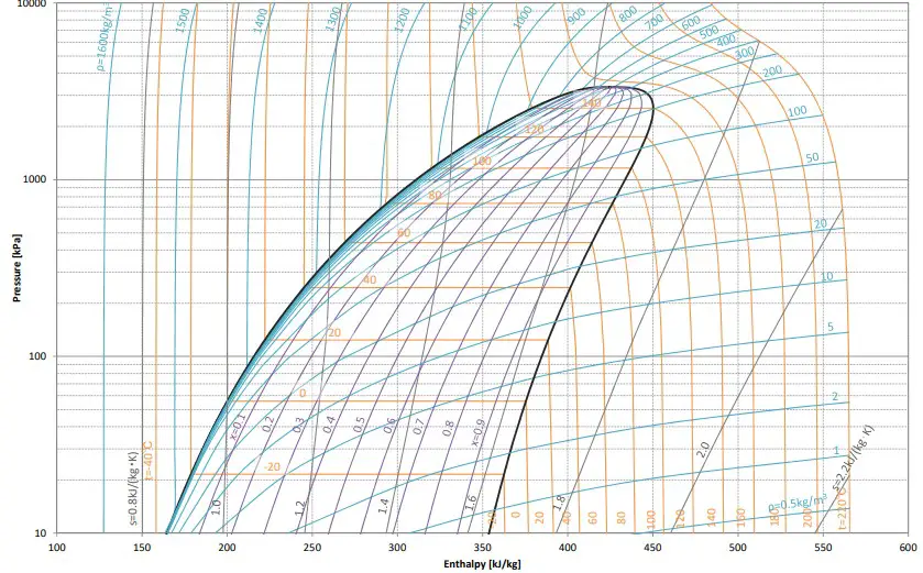
Mollier Diagram R1224yd (Z)
Chemical and physical properties similar to HFC-245fa
Good compatibility with plastics and elastomers
Low thermal conductivity
GWP under 1
Zero-ODP
Low-toxicity
Non-flammable
R1224yd Refrigerant General Applications:
Blowing agen.
Aerosol solvent.
Solvent.
Centrifugal Chiller.
Organic Rankine Cycle.
High-temperature heat pumps.
Lubricants used with R1224yd:
The R1224yd is mutually soluble with refrigerantion oils, such as P O E, that are used with H F C refrigerants, and also with naphthenic oils that are used with H C F C
The solubility in synthetic oil of HFO-based refrigerants such as R1224yd (Z), is higher than that of HFC refrigerants. R1224yd (Z) refrigerant dissolves with both synthetic oil and mineral oil.
Where to learn all about chillers?
We have prepared a complete training in chilled water installations with chillers.
The Chiller R-32 offer approximately 5 to 8% greater capacity, compared to systems that work with R410a.
What should be known about the use of R-32 as a replacement for R-410A in Chillers?
R32 has better efficiency and around 10% more capacity than R410A, depending on the application and system design.
In a new application, R32 stands out as the most efficient and best performing alternative to R410A.
The charge of R32 is about 20% less, compared to R410A. R32 is a relatively inexpensive single component refrigerant, which means it is easier to recycle.
Due to the high discharge temperatures of R-32, the operating range of Chillers with R32 is limited.
For operation in ambient temperature conditions greater than 45 ° C the best options are R452b or R454b.
Manufacturers have selected R-32 for their scroll-type chillers, due to its lower impact on the environment.
Compared to R410A, the Seasonal Energy Efficiency Ratio (SEER) is said to improve by 10%.
Thanks to its lower A2L flammability rating, the R32 can be safely used in chilled water systems.
Although R454B is preferred by many as its direct replacement for R410A, R32 has the advantage of being a non-proprietary one-component gas, has no slip, and has price and availability advantages over its rival.
R-32 refrigerant is made up of a single component, it is easier to handle and recover than other alternatives such as R454B or R452B.
Also, since the R32 is slip-free, it is not necessary to vacuum the system before each charge.
With the R454B and R452B there is the possibility that a disproportionate amount of a component could escape in the event of a leak.
R32 is likely to remain cheaper than R454B and R452B.
As there is no patent on R32, access and availability is guaranteed through many refrigerant suppliers.
Regarding efficiency, calculations and compressor manufacturers show higher efficiency ratings for R32 than for R454B.
R32 with its GWP of 675 has a significantly higher GWP than R454B (GWP 466), however the lower amount of R32 refrigerant used should be considered.
The process of changing from R410A to R32 in a chiller requires various components and configurations to be adjusted, including the expansion valve, liquid line tubing, suction line, and discharge line.
In the process of changing from R410A to R32 in a chiller, it may present an oversized compressor and it may be necessary to change it.
Currently, R32, R452B, R454B is considered in Chillers with scroll compressor as short-term replacement, and in the longer term to R1234ze, R515B, R516A.
Where to learn all about chillers?
We have prepared a complete training in chilled water installations with chillers.